


Cisco 12012 Gigabit Switch Router Card Cage Assembly Replacement Instructions 29
Removing and Replacing a Card Cage Assembly
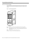
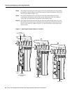
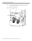
Step 3 Using two hands to support and guide the power supply, slide it into the vacant power
supply bay position. Push the power supply all the way into the power supply bay until
the faceplate makes contact with the front of the bay.
Note All electrical connections between the power supply and the backplane are made
automatically when the power supply is fully inserted in the power supply bay.
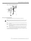
Step 4 Tighten the captive screw on the power supply faceplate.
Step 5 Connect the AC power cord to the power supply AC receptacle. Clip the spring clip over
the power cord plug.
Step 6 Connect the other end of the AC power cord to the source AC receptacle.
Note Do not turn on the power supply power switch at this time.
Repeat Step 2 through Step 6 for the rest of the AC-input power supplies.
Step 7 Verify that any empty power supply bay slots have power supply blanks installed.
Proceed to the section “Checking the Installation” to verify the installation
Replacing a DC-Input Power Supply
Perform the following steps to replace a DC-input power supply:
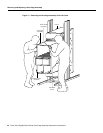
Step 1 Attach an antistatic wrist strap to yourself and to one of the two ESD connection sockets
located on the front edges of the upper card cage or to bare metal on the frame.
Caution To prevent damaging the power supply backplane connector, do not use excessive force
when installing a power supply into the bay.
Step 2 Verify that the power switch on the power supply is in the OFF position.