


20 Cisco 12012 Gigabit Switch Router Card Cage Assembly Replacement Instructions
Removing and Replacing a Card Cage Assembly
Removing the System Grounding
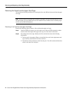
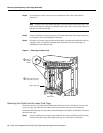
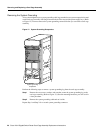
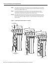
Your system might have two system grounding cable lugs attached to two system receptacles located
on the card cage assembly side flanges between the air filter tray and the power supply bays. (Refer
to Figure 12.) You must remove the system grounding connector before you can remove card cage
assembly.
Figure 12 System Grounding Receptacles
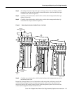
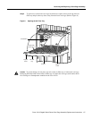
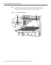
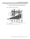
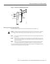
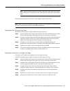
Perform the following steps to remove a system grounding lug from the card cage assembly:
Step 1 Remove the two screws, washers, and nuts that secure the system grounding lug to the
card cage assembly. (Refer to Figure 13.) Save the mounting hardware, you will use it in
a later procedure.
Step 2 Remove the system grounding cable and set it aside.
Repeat Step 1 and Step 2 for a second system grounding connector.
SLOT-0
ROUTE PROCESSOR
SLOT-1
COLL
LINK
TX
RX
RJ-45
MII
RESET
AUX
CONSOLE
EJECT
ACTIVE
0
CARRIER
RX PKT
ACTIVE
1
CARRIER
RX PKT
ACTIVE
2
CARRIER
RX PKT
ACTIVE
3
CARRIER
RX PKT
Q OC-3/STM-POS
ACTIVE
0
CARRIER
RX CELL
OC-12/STM-4 ATM
OC-12/STM-4 POS
ACTIVE
0
CARRIER
RX CELL
ACO/LT
ALARM
CSC
0
FAIL
1
0
1
2
ENABLED
CRITICAL
MAJOR
MINOR
SFC
ALARM 1 ALARM 2
H10899
System grounding
receptacles