


Cisco 12012 Gigabit Switch Router Card Cage Assembly Replacement Instructions 13
Removing and Replacing a Card Cage Assembly
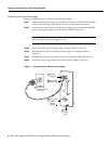
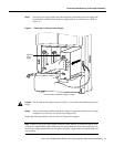
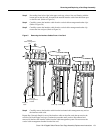
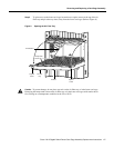
Step 3 Proceeding from left to right in the upper card cage, select a line card. Starting with the
bottom port on the line card, disconnect the network interface cable from the bottom port
on the line card. (Refer to Figure 5a.)
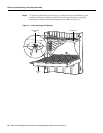
Step 4 Carefully remove the interface cable from the vertical cable-management bracket clips.
(Refer to Figure 5b.)
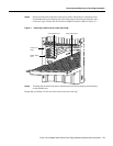
Step 5 Carefully remove the interface cable from the vertical cable-management bracket clip
nearest the line card port. (Refer to Figure 5c.)
Figure 5 Removing the Interface Cables From a Line Card
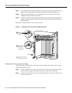
Step 6 Carefully remove the interface cable from the horizontal cable-management tray and set
the interface cable aside.
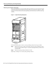
Repeat Step 3 through Step 6 for rest of the interface cables on that line card, then proceed to the
next line card in the upper card cage. Continue the procedure until you have disconnected and
removed all the line card interface cables from the cable-management system. Do not remove the
vertical cable-management bracket from the line card.
ACTIVE
0
CARRIER
RX PKT
ACTIVE
1
CARRIER
RX PKT
ACTIVE
2
CARRIER
RX PKT
ACTIVE
3
CARRIER
RX PKT
a
Chassis
cable-management
tray
Line card
cable-management
bracket
I
nterface
cable
ACTIVE
0
CARRIER
RX PKT
ACTIVE
1
CARRIER
RX PKT
ACTIVE
2
CARRIER
RX PKT
ACTIVE
3
CARRIER
RX PKT
b
Cable clip Cable clips
ACTIVE
0
CARRIER
RX PKT
ACTIVE
1
CARRIER
RX PKT
ACTIVE
2
CARRIER
RX PKT
ACTIVE
3
CARRIER
RX PKT
ACTIVE
0
CARRIER
RX PKT
ACTIVE
1
CARRIER
RX PKT
ACTIVE
2
CARRIER
RX PKT
ACTIVE
3
CARRIER
RX PKT
c
H10880