


26 Cisco 12012 Gigabit Switch Router Card Cage Assembly Replacement Instructions
Removing and Replacing a Card Cage Assembly
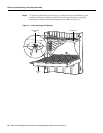
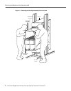
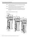
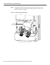
Step 8 Proceeding from bottom port to the top port (line cards with multiple ports only) identify
the interface cable that connects to each line card port. Connect the interface cable to the
line card port. (Refer to Figure 15a.)
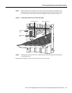
Step 9 Proceeding from bottom port to the top port (line cards with multiple ports only),
carefully press the interface cable into the vertical cable bracket cable clip. (Refer to
Figure 15b.) Avoid any kinks or sharp bends in the interface cable.
Step 10 Proceeding from bottom port to the top port (line cards with multiple ports only), route
the interface cable up the vertical cable bracket and carefully press the interface cable into
the rest of the cable clips. (Refer to Figure 15c.) Avoid any kinks or sharp bends in the
interface cable.
Figure 15 Attaching an Interface Cable to a Line Card
ACTIVE
0
CARRIER
RX PKT
ACTIVE
1
CARRIER
RX PKT
ACTIVE
2
CARRIER
RX PKT
ACTIVE
3
CARRIER
RX PKT
Chassis
cable-management
tray
Line card
cable-management
bracket
a
Interface
cable
ACTIVE
0
CARRIER
RX PKT
ACTIVE
1
CARRIER
RX PKT
ACTIVE
2
CARRIER
RX PKT
ACTIVE
3
CARRIER
RX PKT
Cable clip
b
ACTIVE
0
CARRIER
RX PKT
ACTIVE
1
CARRIER
RX PKT
ACTIVE
2
CARRIER
RX PKT
ACTIVE
3
CARRIER
RX PKT
H10879
Cable clips
c