


14 Cisco 12012 Gigabit Switch Router Card Cage Assembly Replacement Instructions
Removing and Replacing a Card Cage Assembly
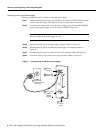
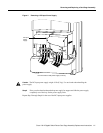
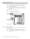
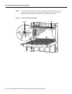
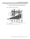
Step 7 Proceeding from left to right in the upper card cage, select a line card and loosen the two
captive screws located at the top and bottom of the line card (Refer to Figure 6a.)
Step 8 Pivot the two card ejector levers out, away from the card to unseat the card from the
backplane connector. (Refer to Figure 6b.)
Step 9 Grasp the card carrier edge with one hand and place your other hand under the carrier to
support it. (Refer to Figure 6c.) Slide the card out of the slot and place it immediately on
the antistatic mat.
Repeat Step 7 through Step 9 for the rest of the line cards.
Figure 6 Removing a Line Card From the Upper Card Cage
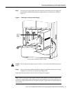
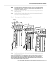
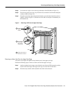
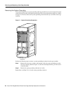
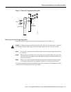
Removing a RP From the Upper Card Cage
The RP can occupy slot 0 through 11 in the upper card cage. Perform the following steps to remove
a RP from the upper card cage:
Step 1 Attach an antistatic wrist strap to yourself and to one of the two ESD connection sockets
located on the front edges of the upper card cage or to bare metal on the frame.
Step 2 Disconnect all of the interface cables attached to RP interface connector. Carefully set the
interface cables aside.
SLOT-0
GIGABIT ROUTE PROCESSOR
SLOT-1
COLL
LINK
TX
RX
RJ-45
MII
RESET
AUX
CONSOLE
EJECT
ACTIVE
0
CARRIER
RX PKT
ACTIVE
1
CARRIER
RX PKT
ACTIVE
2
CARRIER
RX PKT
ACTIVE
3
CARRIER
RX PKT
Q OC-3/STM-POS
ACTIVE
0
CARRIER
RX CELL
OC-12/STM-4 ATM
OC-12/STM-4 POS
ACTIVE
0
CARRIER
RX CELL
ACO/LT
ALARM 1 ALARM 2
ALARM
CSC
0
FAIL
1
0
1
2
ENABLED
CRITICAL
MAJOR
MINOR
SFC
ACTIVE
0
CARRIER
RX PKT
ACTIVE
1
CARRIER
RX PKT
ACTIVE
2
CARRIER
RX PKT
ACTIVE
3
CARRIER
RX PKT
Q OC-3/STM-POS
H10705
Loosen
captive
screws
Line card
Pivot ejector
levers away
from card to
unseat card
Grasp card carrier to
slide card out of slot
a
c
b