


28 Cisco 12012 Gigabit Switch Router Card Cage Assembly Replacement Instructions
Removing and Replacing a Card Cage Assembly
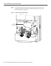
Installing the System Grounding
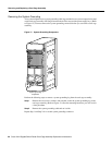
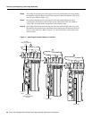
Your system might have two system grounding cable lugs. The system grounding receptacles are
located on the card cage assembly side flanges between the air filter tray and the power supply bay.
(Refer to Figure 12.)
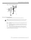
Perform the following steps to install the system grounding lugs to the card cage assembly:
Step 1 Position the system ground lug over the card cage assembly system grounding receptacle.
Step 2 Secure the system grounding lug to the receptacle with two sets of screws, washers, and
nuts. (Refer to Figure 13.)
Repeat Step 1 and Step 2 for a second system grounding connection.
Replacing the Power Supplies
This section provides procedures for replacing an AC-input power supply and a DC-input power
supply. Select the procedure appropriate for your system.
Caution Always wear an antistatic wrist strap to prevent ESD when removing and replacing a
power supply.
Replacing an AC-Input Power Supply
Perform the following steps to replace an AC-input power supply:
Step 1 Attach an antistatic wrist strap to yourself and to one of the two ESD connection sockets
located on the front edges of the upper card cage or to bare metal on the frame.
Step 2 Verify that the power switch on the power supply is in the STANDBY position.
Caution To prevent damaging the power supply backplane connector, do not use excessive force
when installing a power supply into the bay.
Note The power supply bay positions are designated A1, A2, B1, and B2, from left to
right. Install power supplies in the bay in the following order: A1, B1, A2, and B2. Any
power supply bay position that does not have a power supply installed must have a power
supply blank installed to maintain airflow and for EMI considerations.