


1-3
Cisco AVS 3120 Application Velocity System Hardware Installation Guide
OL-11805-01
Chapter 1 Product Overview
Ports and Connectors
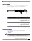
Rear Panel Features
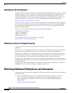
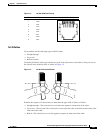
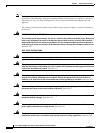
The rear panel contains the AC power receptacle, power switch, Ethernet connectors, and the
console/serial connector. Figure 1-2 illustrates the rear panel ports and connectors.
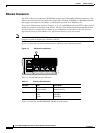
Figure 1-2 Rear Panel View
Ports and Connectors
The AVS 3120 supports the following port connectors on the rear of the chassis:
• Ethernet Connectors
• Console Port
Warning
To avoid electric shock, do not connect safety extra-low voltage (SELV) circuits to telephone-network
voltage (TNV) circuits. LAN ports contain SELV circuits, and WAN ports contain TNV circuits. Some
LAN and WAN ports both use RJ-45 connectors. Use caution when connecting cables.
Statement 1021
1 USB ports (not supported) 7 Power indicator. Off indicates no power.
Green when the power supply is running.
2 Management port (not supported) 8 AC power receptacle
3 RJ-45 Ethernet connectors with
10/100/1000-Mbit/s operation
9 Auxiliary port (not supported)
4 External compact flash device (not used) 10 Compact flash indicator. Off when the
compact flash device is not being accessed.
Blinks green when the compact flash device
is being accessed.
5 Console serial port (see Figure 1-6) 11 Status indicator. Blinks green while the
power-up diagnostics are running or the
system is booting. Solid green when the
system has passed power-up diagnostics.
Solid amber when the power-up diagnostics
have failed.
6 Power switch 12 Power indicator. Off indicates no power.
Green when the power supply is running.
153107
LINK SPD
2
LINK SPD
3
LINK SPD
4
LINK SPD
1
MGMT
USB2
USB1
FLASH
CONSOLE
AUX
POWER
STATUS
FLASH
2
1
4
5
6
7
8
9
10
11
12
3