


3-6
Cisco AVS 3120 Application Velocity System Hardware Installation Guide
OL-11805-01
Chapter 3 Installing the AVS 3120
Installing Your AVS 3120
Connecting Cables
Warning
Do not work on the system or connect or disconnect cables during periods of lightning activity.
Statement 1001
To connect network and console cables to your AVS 3120:
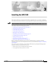
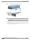
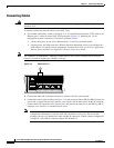
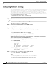
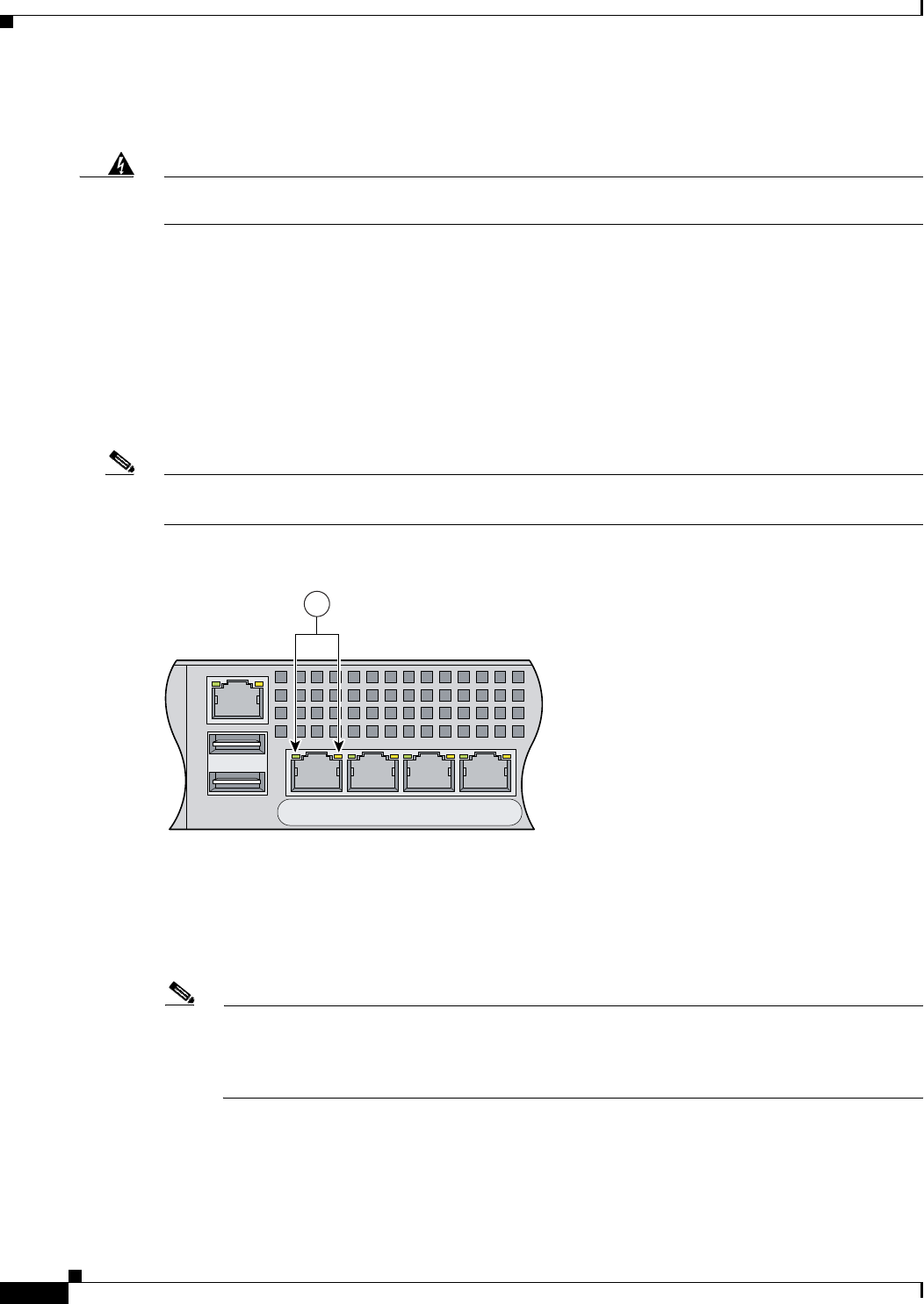
1. For network connections, connect a Category 3, 4, or 5 unshielded twisted-pair (UTP) cable to the
Ethernet port 1 connector on the AVS 3120 back panel (Figure 3-3). Ethernet port 1 is for
management console connectivity. Note that in software version:
• 5.0, the other ports are not active. Ethernet port 1 is used for all network traffic.
• 6.0 and greater, the other ports have different functions depending on how you configure the
AVS software. For details on port assignments, see the Release Note for the Cisco Application
Velocity System and the Cisco Application Velocity System User Guide.
Note The 100BASE-TX/1000BASE-T Ethernet standard requires that you use standard four twisted-pair
Category 5e cable at lengths up to 328.08 ft. (100 m).
Figure 3-3 Ethernet Port 1
2.
Connect the other end of the network cables to a hub or switch in your network.
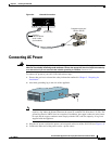
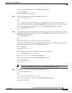
3. Connect the console cable as shown in Figure 3-4 so that you have either a DB-9 or DB-25 connector
on one end, as required by the serial port for your console, and the other end is the RJ-45 connector.
Connect the RJ-45 connector to the console port, and connect the other end to the DB-9 or DB-25
connector on a console or a communications server.
Note Use the console port to connect to a computer, console, or communications server to enter
configuration commands. Locate the serial cable from the accessory kit. The serial cable
assembly consists of a 180/rollover cable with RJ-45 connectors, a DB-9 connector adapter PN
74-0495-01, and a DB-25 connector adapter PN 29-0810-01.
143773
USB2
USB1
LNK SPD
2
LNK SPD
3
LNK SPD
4
LNK SPD
1
MGMT
1