


3-7
Cisco AVS 3120 Application Velocity System Hardware Installation Guide
OL-11805-01
Chapter 3 Installing the AVS 3120
Connecting AC Power
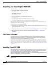
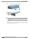
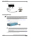
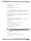
Figure 3-4 Console Connection
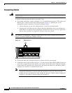
Connecting AC Power
Warning
This equipment must be grounded. Never defeat the ground conductor or
operate the equipment in the
absence of a suitably installed ground conductor.
Contact the appropriate electrical inspection authority
or an electrician if you are uncertain that suitable grounding is available.
Statement 1024
To connect AC power to your AVS 3120, follow these steps:
1. Ensure that you have reviewed the safety information outlined in Chapter 2, “Preparing for
Installation.”
2. Attach the grounding lug to the side of the appliance.
Note Use 8-32 screws to connect a copper standard barrel grounding lug to the holes. The appliance
requires a lug where the distance between the center of each hole is 0.56 inches (1.42 cm). The
ground lug must be NRTL listed or recognized. In addition, the copper conductor (wires) must
be used and the copper conductor must comply with the NEC code for ampacity. A lug is not
supplied with the appliance.
3. Plug the AC power cord into the power cord receptacle at the rear of the AVS 3120 (see Figure 1-2).
4. Connect the other end of the power cord to a power source.
114418
RJ-45 to
DB-9 or DB-25
serial cable
(null-modem)
Computer serial port
DB-9 or DB-25
FLASH
CONSOLE
AUX
POWER
STATUS
FLASH
Console
port (RJ-45)
143780
C
isco A
V
S
3
12
0
series
A
p
p
lic
a
tio
n
V
e
lo
c
it
y
S
y
s
te
m