


Cisco UCS Cisco UCS C220 M3 High-Density Rack Server (Small Form Factor Disk Drive Model)
58
SUPPLEMENTAL MATERIAL
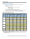
CPUs and DIMMs
Physical Layout
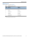
Each CPU has four DIMM channels:
■ CPU1 has channels A, B, C, and D
■ CPU2 has channels E, F, G, and H
Each DIMM channel has two banks: bank 1 and bank 2. The blue-colored DIMM slots are for bank 1 and the
black-colored slots are for bank 2.
As an example, DIMM slots A1, B1, C1, and D1 belong to bank 1, while A2, B2, C2, and D2 belong to bank 2.
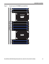
Figure 7 shows how banks and channels are physically laid out on the motherboard. The DIMM slots on the
right (channels A, B, C, and D) are associated with CPU1, while the DIMM slots on the left (channels E, F, G,
and H) are associated with CPU2. The bank 1 (blue) DIMM slots are always located farther away from a CPU
than the corresponding bank 2 (black) slots. Bank 1 slots (blue) are populated before bank 2 slots (black).
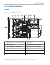
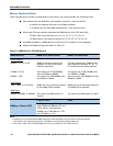
7 CPUs and heatsinks (two) 16 Power supplies (two, hot-swappable
access through rear panel)
8 Integrated RAID on motherboard, and mini-SAS
connectors
17 RTC battery on motherboard
9 Mezzanine RAID card, mini-SAS connectors
SAS1 and SAS2
18 Software RAID 5 header (RAID key).