


2-14
Cisco Aironet 1000 Series Lightweight Access Point Hardware Installation Guide
OL-9403-04
Chapter 2 Installing the Access Point
Mounting Overview
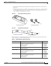
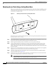
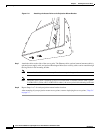
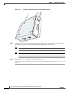
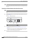
Figure 2-11 Attaching the Access Point to the Projection-Mount Bracket
Step 7
Attach the cables to the sides of the access point. The Ethernet cable, optional external antenna cable(s),
optional power supply cable, and optional Kensington MicroSaver security cables can be routed through
the large holes in the mounting bracket.
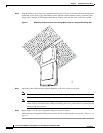
Note Ensure that the cables are routed away from the access point integrated antennas.
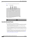
Note When the access point is powered up and is associated with a controller (Power LED is green,
2.4 GHz LED is yellow, and 5.4 GHz LED is amber), the access point is broadcasting its beacon.
Step 8 Repeat Steps 1 to 7 for each projection-mount bracket location.
After mounting all your projection-mount access points, return to deploying the access points, "Step 3-c"
on page 2-7.
135671