


2-19
Cisco Aironet 1000 Series Lightweight Access Point Hardware Installation Guide
OL-9403-04
Chapter 2 Installing the Access Point
Powering Up the Access Point
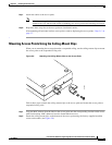
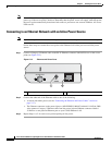
Connecting to an Ethernet Network with Local Power
Note If your access point is connected to in-line power, do not connect the power module to the access point.
Follow these steps to connect the access point to an Ethernet LAN when you are using a local power
source:
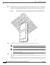
Step 1 Connect a Category 5 Ethernet cable to the RJ-45 Ethernet connector labeled Ethernet on the access
point (see Figure 2-13).
Step 2 Plug the other end of the Ethernet cable into an non-powered Ethernet port on your 10/100 Ethernet
LAN.
Step 3 Connect the power module output connector to the access point’s 48-VDC power port (see Figure 2-13).
Step 4 Plug the power module power cord into an approved 100- to 240-VAC outlet.
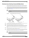
Powering Up the Access Point
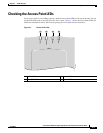
After you power up the access point, it begins a power-up sequence that you can check by observing the
access point LEDs. The red Alarm LED turns on for about 15 to 20 seconds and then all LEDs blink
sequentially back and forth, indicating that the access point is trying to find a controller. Refer to
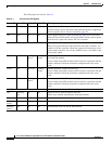
“Checking the Access Point LEDs” section on page 3-3 for LED descriptions.
After the access point finds the controller, the access point downloads new operating system code if the
access point code version differs from the controller code version. During the download process, all
access point LEDs blink simultaneously. When the operating system download is successful, the access
point reboots.
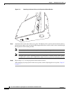
Normal operation is indicated when the Alarm LED is off, the Power LED is green, and the 2.4 GHz and
5 GHz LEDs are blinking to indicate radio activity.
If no LEDs are on, the access point might not be receiving sufficient power.
If all the LEDs blink sequentially for more than five minutes, the access point is unable to find its
primary, secondary, or tertiary controllers. Check the connection between the access point and its
controllers and ensure they are on the same subnet or that the access point has a route back to its primary,
secondary, and tertiary controllers. If the access point is not on the same subnet as the controllers, ensure
there is a properly configured DHCP server on the same subnet as the access point. See the “Using DHCP
Option 43” section on page 3-2 for DHCP information.
Note To allow client roaming between access points, the access points must be on the same subnet.
Note Connect only one power source to the access point, for example: When using in-line power, do not
connect the power module to the access point.