


1-7
Cisco PNNI Network Planning Guide for MGX and SES Products, Release 5
Part Number OL-3847-01 Rev. D0, April, 2004
Chapter 1 Introduction to PNNI
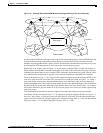
The Hierarchical PNNI Network Topology
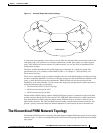
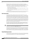
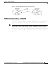
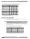
Figure 1-4 Simple Node Representation
Other peer groups receive information about the outside links leading to the local peer group, but no
internal peer group information is advertised to other peer groups. The advantage of simple node
representation is that it keeps the PNNI database within each node smaller than that for complex node
representation. Simple node representation also requires fewer resources on the LGN that represents the
peer group. The disadvantage it that the true cost of crossing a peer group is hidden by simple node
representation. In some networks, this can cause connections to be routed over less desirable routes.
Complex Node Representation
The alternative to simple node representation is complex node representation. When complex node
representation is enabled for a LGN, the LGN presents additional information about the peer group it
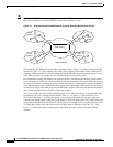
represents. Figure 1-5 illustrates complex node representation.
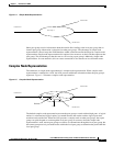
Figure 1-5 Complex Node Representation
The default complex node representation presents the peer group as a node with multiple ports. A logical
nucleus is calculated and logical spokes are created between the nucleus and the logical ports that
terminate each outside link. When the LGN presents a complex node to other peer groups, those peer
groups can pick the path to use through the local peer group. In contrast, when the simple node
representation is used, remote peer groups can choose to communicate through the local peer group, but
the remote group must rely on border nodes within the local peer group to determine the path within the
local peer group.
Outside link 1
Outside link 2
Outside link 3
Outside link 4
Peer Group A
Outside link 1
Outside link 2
Outside link 3
Outside link 4
Peer Group A
Nucleus
Spoke