


2-5
Cisco PNNI Network Planning Guide for MGX and SES Products, Release 5
Part Number OL-3847-01 Rev. D0, April, 2004
Chapter 2 Interoperability and Performance Planning
Physical Network Planning
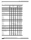
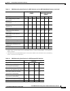
Table 2-3 identifies some important differences between the way connections are counted on the switch
and in CWM. For example, although all connection types are counted as one connection on the switch,
SVCs and pass-through connections are not included when calculating the connection limit for CWM.
DAX SPVCs, however, are counted as two connections when calculating the connection limit for CWM.
The real issue is what happens if you configure a CWM-managed switch with only DAX SPVCs. In this
example, the switch can support 250K DAX SPVCs, but CWM can support only 125K DAX SPVCs.
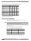
To determine the actual connection limits for a CWM-managed switch, multiply the number of each
connection type by the unit cost in each column of Table 2-3. The total for each column must not exceed
250K.
Physical Network Planning
The PNNI switches described in this guide can reroute connections and adjust to equipment or link
failures only when the physical network has been designed to use redundant hardware and links. When
designing a PNNI network, consider doing the following:
• Install redundant hardware in switches
• Install parallel links between adjacent switches
• Set up multiple links between adjacent peer groups
• Use multiple links when connecting to an external network
• Provide multiple communication paths between any two nodes that will communicate with each
other
The following sections provide additional information on these guidelines.
Install Redundant Hardware in Switches
The switches described in this guide support redundant power supplies, Processor Switch Module
(PXM) cards, line cards, and trunk cards. Although PNNI can reroute calls, using redundant hardware
can improve network stability and performance by preventing reroutes caused by hardware failure.
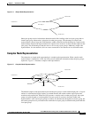
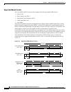
Parallel Links Between Adjacent Switches
When there are two or more links between adjacent switches, those links are called parallel links.
Parallel links support more traffic than single links and provide link redundancy for each other. If one
link fails, the other is still available. Another way to provide link redundancy is to use the Automatic
Protection System (APS), which provides link redundancy for optical interfaces.
By default, MGX switches load balance across parallel links. Load balancing uses one of four methods
to balance the traffic load over parallel links. The goal is to prevent any single link from being overloaded
when other links have available bandwidth. Load balancing is described in more detail in Chapter 4,
“Planning Intermediate Route Selection.”