


CHAPTER
3-1
Cisco PNNI Network Planning Guide for MGX and SES Products, Release 5
Part Number OL-3847-01 Rev. D0, April, 2004
3
Address and Closed User Group Planning
Proper address planning can greatly increase the performance of a PNNI WAN. Although a PNNI WAN
can support almost any addressing scheme, an uncoordinated address scheme can cause excessive
address advertisement and needless rerouting, both of which reduce network performance. A good
addressing plan is one which is hierarchical in nature and thus summarizes simply and efficiently.
The PNNI Closed User Group (CUG) feature allows the network administrator to define user groups of
ATM addresses. Once these user groups are defined, the administrator can control how users within the
groups communicate with other group members and with those outside the group.
This chapter provides an address planning overview, a CUG planning overview, and general guidelines
for creating an ATM address plan and a CUG plan.
Note All Cisco MGX and SES switch products ship with default addresses. These defaults are provided for
lab evaluations of these products. Before the switch is deployed, Cisco Systems advises you to
reconfigure the default addresses using the address plan guidelines in this chapter.
Address Planning Overview
Every route across a PNNI network is determined by two ATM End Station Addresses (AESAs), a source
and a destination. When a connection is being established, the source PNNI routing node looks up the
destination address in PNNI routing tables. If the routing tables do not contain a satisfactory predefined
route, the switch uses the PNNI topology database to search for a route. Routing decisions are made
based on many criteria as discussed in Chapter 4, “Planning Intermediate Route Selection.” This section
focuses on how proper address planning can make PNNI routing more efficient.
Note The source end of a connection is also called the master end of the connection, as the master end is
responsible for initiating the connection. The destination end is also called the slave end.
PNNI provides both a routing protocol and a signaling protocol. The routing protocol is used to build a
topology database and create a route table of all the reachable AESAs. The signalling protocol is used
to establish calls across the PNNI network. When initiating a call, the signaling protocol refers to the
routing table or topology database to locate a route to the destination ATM address.
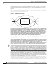
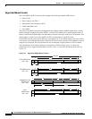
To understand the importance of an address plan, consider how PNNI would respond if there were no
plan. Consider a network with 100 non-coordinated destination ATM addresses. Assume that all
addresses were chosen at random. To enable access to all destinations, PNNI has to create a separate
route for each of the 100 destinations, and this has to be repeated on every switch in the network.