


3-13
Cisco PNNI Network Planning Guide for MGX and SES Products, Release 5
Part Number OL-3847-01 Rev. D0, April, 2004
Chapter 3 Address and Closed User Group Planning
Planning Address Configuration Settings
To enable communications over AINI and IISP links, static addresses must be configured on the end of
each link as described in the following guides:
• Cisco MGX 8850 (PXM1E/PXM45), Cisco MGX 8950, Cisco MGX 8830, and Cisco MGX 8880
Configuration Guide, Release 5
• Cisco SES PNNI Controller Software Configuration Guide, Release 3
There is no default prefix for AINI and IISP links, and because these protocols are used on separate link
types (not PNNI links), there is no requirement to configure prefixes for AINI and IISP links. However,
the PNNI database within each network does store the static addresses, so if there are multiple static
addresses that have the same prefix, you can improve PNNI routing efficiency and save configuration
time by configuring a summary address prefix that covers multiple ATM addresses. The summary
address prefix is a partial ATM address and represents all destinations for which the most significant
bytes of the ATM address match the summary address.
When planning AINI and IISP prefixes for your WAN, consider the following possibilities:
• If you are connecting to a network managed by another authority, that authority will probably issue
the destination addresses to you.
• The same address or summary address can be configured on more than one port, and multiple
addresses can be configured on each port.
• Because the destination devices are not part of the PNNI network, IISP address prefixes do not have
to conform to the PNNI level, peer group ID, or node prefix.
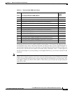
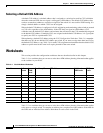
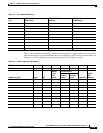
Enter any AINI or IISP prefixes into the Port Address Worksheet, Table 3-5, which appears at the end of
this chapter.
Selecting Static Addresses for UNI Ports
When CPE devices do not support ILMI, they cannot automatically gain an ATM address from the node,
so you must configure a static ATM address on the port that leads to the CPE. You can add up to 255
static addresses on each port, if this number remains within the maximum addresses per node limit.
Multiple ports can be configured with the same static address, but there should be just one CPE that uses
each address. When a port leads to multiple CPE that use a common prefix, you can use a summary
address to create a single entry that routes to multiple CPE.
Enter the static addresses or summary addresses into the Port Address Worksheet, Table 3-5, which
appears at the end of this chapter.
Additional Guidelines for Creating an Address Plan
The following are guidelines for creating an address plan:
• Select the lowest-level PNNI level that will enable future expansion.
• Use PNNI levels that fall on 8-byte boundaries. This improves scalability and makes the PNNI level
number easier to work with.
• Use default values for as many entities as possible.
• Use AINI and IISP links to connect to public WANs.
• Do not use Cisco node address defaults in public WANs.