


3-2
Cisco PNNI Network Planning Guide for MGX and SES Products, Release 5
Part Number OL-3847-01 Rev. D0, April, 2004
Chapter 3 Address and Closed User Group Planning
Address Planning Overview
Furthermore, PNNI switches exchange data with all other nodes in the peer group, so lots of address
information would be transmitted constantly throughout the network as PNNI monitors the network
topology.
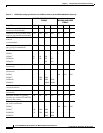
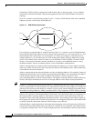
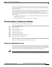
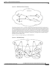
Now let’s consider a more efficient example. Figure 3-1 shows a PNNI network with some simplified
addresses in place of the 20-byte ATM addresses.
Figure 3-1 PNNI Addressing Example
For consistency, assume that the six switches shown in Figure 3-1 connect to a total of 100 destinations.
Notice that the destination addresses for the external lines connected to A.1 all use the prefix A.1, and
the destination lines connected to A.2 use the prefix A.2. When you configure a common prefix for
multiple addresses, you can reduce the size of the routing table and the topology database by storing
routes to the address prefix, instead of routes to every destination. In this example, all nodes in Peer
Group A store routes to the other switches, but there is no need to store additional routes for every
destination address. The use of address prefixes is also called address summarization.
Address summarization also makes network management easier because you do not need to manually
enter every AESA into the source nodes. Instead, you define a PNNI address prefix, which summarizes
all destinations that share that prefix.
Address summarization does not preclude the use of non-conforming addresses. For example, if network
management dictates the use of a specific non-conforming ATM address for a destination, that address
can be manually entered at the switch, and PNNI will advertise a route to that device. The
non-conforming address is called a foreign address. The support of foreign addresses makes PNNI more
flexible, but keep in mind that excessive use of foreign addresses does impact switch performance.
Tip Chapter 4, “Planning Intermediate Route Selection,” describes how up to five routes can be stored in a
total of 10 route tables for each destination. To understand the impact of foreign addresses, multiply the
potential of 50 routes times the number of switches in a peer group, and then multiply that number times
the number of foreign addresses. Address summarization is a key component in PNNI address planning.
When a call is placed to a destination address, PNNI refers to the destination addresses and prefixes in
the routing tables or topology database. After the best route is chosen to the destination switch, the
destination switch selects the appropriate destination interface by searching internal address tables for
the longest prefix match. When a switch and its interfaces are configured with prefixes that enable PNNI
to quickly locate the destination interface, PNNI routing is most efficient.
Although address summarization does make network management easier and routing more efficient, it
can be misused and make PNNI routing less efficient. Consider the case where the same address prefix
is assigned to multiple nodes. This is a valid configuration, but it can lead PNNI to unnecessarily reroute
89686
A1
A.11
A.12
A.13
A.21
A.22
A.23
A2
A3
A4
A5
Peer group A
A6