


2-6
Cisco PNNI Network Planning Guide for MGX and SES Products, Release 5
Part Number OL-3847-01 Rev. D0, April, 2004
Chapter 2 Interoperability and Performance Planning
Planning Guidelines for Individual Peer Groups
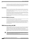
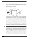
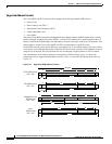
Multiple Links Between Adjacent Peer Groups
Communications between two peer groups takes place through two border nodes. Parallel links between
two border nodes improves reliability. Adding additional border nodes to handle communications
between two peer groups provides alternative routing paths and prevents network outages caused by a
single node failure.
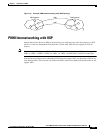
Multiple Links to an External Network
An external network link is any non-PNNI network link. External network links include AINI and IISP
links. As with internal network links, consider using parallel links and additional border nodes to provide
alternative paths to external networks. When you configure multiple static links to an external network,
remember to duplicate the ATM address advertisement configuration on all redundant links.
Multiple Paths Between Network Nodes
It is good design practice to ensure that there are at least two different paths between any pair of nodes
that will communicate with each other. A pair of redundant links is one path. If one switch site is
damaged by fire or earthquake, there should be at least one other switch that can provide an alternative
path between the source and destination switches.
It is also a good design practice to distribute paths across multiple service modules so that a service
module failure does not disrupt all communications between two nodes.
Planning Guidelines for Individual Peer Groups
The first step in planning a PNNI topology is to determine if all network nodes will participate in one
peer group or in hierarchical peer groups. The single and hierarchical peer group topologies are
introduced in Chapter 1, “Introduction to PNNI.” When a network grows beyond the capabilities of a
single peer group, you must use the hierarchical peer group topology.
The planning for a single peer group topology is the same as the planning for a single peer group within
a hierarchical PNNI network. The difference between planning for a single peer group network and
planning for a hierarchical network is that for hierarchical networks, you have to plan the
communications between peer groups. The following list summarizes the capabilities and guidelines for
a single peer group:
• For networks with less than 100 nodes, Cisco Systems recommends using a single peer group
topology.
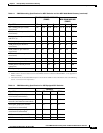
• A single peer group supports up to 160 nodes as described in Table 2-1.
• All nodes within a single peer group must be able to communicate with each other over a path of
inside links.
• PNNI can route calls through a maximum of 20 nodes within a single peer group. The structure of
the peer group should be such that no node is more than 19 hops from any other node.
• As the number of nodes in a single peer group grows, the network and system resource requirements
for each node grows.