


3-15
Cisco PNNI Network Planning Guide for MGX and SES Products, Release 5
Part Number OL-3847-01 Rev. D0, April, 2004
Chapter 3 Address and Closed User Group Planning
Planning CUG Configuration Settings
CUG membership is supported as follows:
• An ATM address or ATM address prefix can be a member of up to 100 CUGs.
• CUGs can be provisioned on up to 200 ATM addresses or prefixes.
• The maximum number of CUGs is 65535.
• An ATM address to which a CUG is assigned can use either the NSAP or E.164 address format.
Note The CUG feature is not supported on nodes which are configured with right-justified E.164 addresses using
the cnfe164justify command.
Planning CUG Configuration Settings
The following sections introduce and provide planning guidelines for the CUG configuration
parameters.
Selecting an Interlock Code
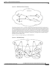
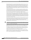
A CUG is established by assigning the same 24-byte interlock code to two or more prefixes or AESAs
on a PNNI network. All prefixes and addresses that share the same interlock code are considered part of
the same CUG and can establish connections amongst themselves, unless these connections are blocked
by configuration options.
When selecting an interlock code, consider the following guidelines:
• The interlock codes should be managed so that an existing interlock code is not selected for a new
CUG.
• Other than being unique to a single CUG, there is no requirement on the contents of the interlock
code.
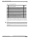
When planning a CUG, consider using the CUG Configuration Worksheet, Table 3-6, which appears at
the end of this chapter. Each CUG uses only one interlock code, so place that code in the first row of the
worksheet.
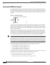
Selecting an Index
A CUG index is a number that the administrator specifies when making an address or prefix part of a
CUG. The CUG index is mapped to the appropriate interlock code within the switch. During CPE
configuration, the appropriate CUG index is configured on the CPE to match the index already defined
on the node. When the CPE requests a call, it supplies the index, which is used by the switch to identify
the appropriate CUG.
When specifying an index, consider the following guidelines:
• Within each switch, the same, unique index number should be used for all CUG assignments that
share the same interlock code.
• The interlock code is not used outside of the switch. Once the index number is mapped to the
interlock code, the interlock code is used for all network communications.
• The CPE cannot use the index without further configuration.