


Receptacles, Cables, and Pinouts
PA-2H Dual-Port HSSI Port Adapter Installation and Configuration
1-4
Receptacles, Cables, and Pinouts
This section provides information about the HSSI cables you should use with the HSSI port adapter.
Two types of cables are available for use with the HSSI port adapter: the HSSI interface cable used
to connect your router to an external DSU (and HSSI network) and a null modem cable, which
allows you to connect two routers back to back. Both HSSI cables are available only from Cisco
systems and conform to EIA/TIA-612 and EIA/TIA-613 specifications.
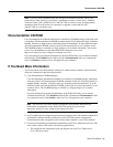
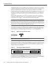
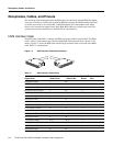
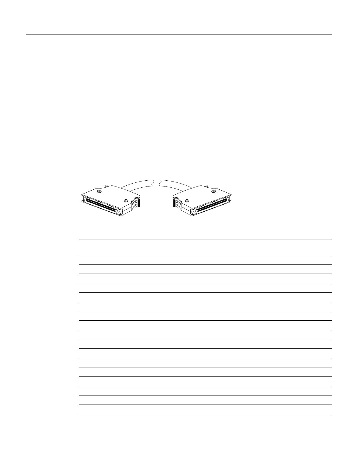
HSSI Interface Cable
The HSSI cable (CAB-HSI1=) connects the HSSI port adapter with the external DSU. The HSSI
cable is 10-feet (3.048 meters) long. The maximum HSSI cable length allowed is 50 feet (15.24
meters). Figure 1-5 shows the HSSI cable and the 50-pin connector used at each end of the HSSI
cable. Table 1-1 lists the pinout.
Figure 1-5 HSSI Interface Cable and Connectors
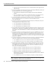
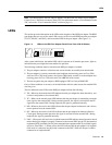
Table 1-1 HSSI Interface Cable Pinout
Signal Name + Side Pin No. – Side Pin No.
Direction
1
Router DSU
1 Router is + side (DTE). DSU is – side (DCE).
SG (Signal Ground) 1 26 —
RT (Receive Timing) 2 27 <—
CA (DCE Available) 3 28 <—
RD (Receive Data reserved) 4 29 <—
LC (Loopback circuit C) 5 30 <—
ST (Send Timing) 6 31 <—
SG (Signal Ground) 7 32 —
TA (DTE Available) 8 33 —>
TT (Terminal Timing) 9 34 —>
LA (Loopback circuit A) 10 35 —>
SD (Send Data) 11 36 —>
LB (Loopback circuit B) 12 37 —>
SG (Signal Ground) 13 38 —
5 (Ancillary to DCE) 14–18 39–43 —>
SG (Signal Ground) 19 44 —
5 (Ancillary from DCE) 20–24 45–49 <—
SG (Signal Ground) 25 50 —
H5691