


Port Adapter Locations on the Supported Platforms
PA-FE-TX and PA-FE-FX Fast Ethernet 100BaseT Port Adapter Installation and Configuration
1-4
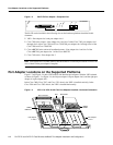
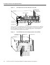
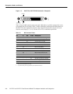
Figure 1-5 Port Adapter Slots in the Cisco 7200 Series—Cisco 7206
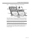
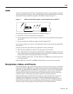
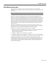
Figure 1-6 shows a Cisco uBR7200 series router with port adapters installed. In theCisco uBR7246,
port adapter slot 1 is in the upper left position, and port adapter slot 2 is in the upper right position.
In the Cisco uBR7223, port adapter slot 1 is in the upper right position. The port adapters are
recessed into the chassis just below the I/O controller.
Figure 1-6 Cisco uBR7200 Series with Port Adapters Installed—Cisco uBR7246
H6422
2
ETHERNET 10BT
ENABLED
0
2
1
3
LINK
0
1
2
3
ENABLED
MII
LINK
RJ45
FAST ETHERNET
0
0
4
1
3
5
6
Port adapter slot 5
Port adapter slot 3
Port adapter slot 1
FAST SERIAL
EN
TD
TC
RD
RC
LB
CD
TD
TC
RD
RC
LB
CD
TD
TC
RD
RC
LB
CD
TD
TC
RD
RC
LB
CD
TOKEN RING
0
1
2
3
ETHERNET-10BFL
EN
RX
0
1
2
3
4
TX
RX
TX
RX
TX
RX
TX
RX
TX
Blank port adapter
Port adapter slot 6
Port adapter slot 4
Port adapter slot 2
MII
EN
RJ45
EN
RJ45
LINK
1O PWR
OK
RJ-45
CPU RESET
FAST ETHERNET INPUT/OUTPUT CONTROLLER
ENABLED
PCMCIA
EJECT
SLOT 0
SLOT 1
FE MII
Port adapter slot 0
H11323
Cable modem card slot 3
Cable modem card slot 4
Cable modem card slot 5
Cable modem card slot 6
Port adapter slot 0
(I/O controller)
Port adapter slot 1
(blank)
Port adapter slot 2