


Performing a Basic Configuration
PA-FE-TX and PA-FE-FX Fast Ethernet 100BaseT Port Adapter Installation and Configuration
8-6
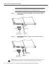
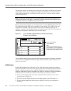
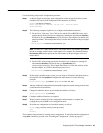
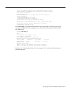
Figure 8-4 Port Adapter Slot Numbering—Cisco 7120 Series
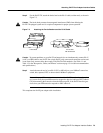
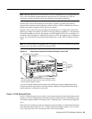
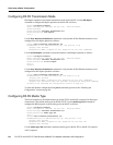
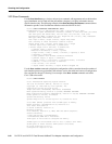
Slots in the Cisco 7140 series are numbered as shown Figure 8-5. The fixed LAN interface is slot 0,
the fixed WAN interfaces are slots 1 and 2, and the modular port adapter interface is slot 4. Slot 3 is
not used. Slot 5 is the service adapter.
Figure 8-5 Port Adapter Slot Numbering—Cisco 7140 Series
Performing a Basic Configuration
Following are instructions for a basic configuration enabling an interface and specifying IP routing.
You might also need to enter other configuration subcommands, depending on the requirements for
your system configuration and the protocols you plan to route on the interface. For more information
on FE interface configurations on supported platforms, refer to the modular configuration and
modular command reference publications in the Cisco IOS software configuration documentation
set that corresponds to the software release installed on your Cisco hardware.
In the following procedure, press the Return key after each step unless otherwise noted. At any time
you can exit the privileged level and return to the user level by entering disable at the prompt as
follows:
Router# disable
Router>
SLOT 0 SLOT 1
0
2
FE 0 / 0 FE
AUX
7120 - AE3
RXTX
E3
RX
EN
CEL CARALM
5
I
CONS
ACT
0 / 1
ACT
LNK
0
LNK
1
PWR
SYS
RDY
Slot 1 Slot 0
Slot 3
Slot 5
18498
SLOT 0 SLOT 1
AC OK
DC OK
OTF
AC OK
DC OK
OTF
5
155 - MM
RX
RX
EN
CEL CARALM
TX
I
155 - MM
CONS
FE 0 / 0 FE
ACT
0 / 1
AUX
0
2
RX
7140 - 2MM3
RX
EN
CEL CARALM
TX
ACT
LNK
0
LNK
1
PWR
SYS
RDY
EN
ERROR
BOOT
RESETSM-EC-DS
18499
Slot 1 Slot 0 Slot 2
Slot 4Slot 5