


Identifying Chassis Slot, Port Adapter Slot, and PA-FE Interface Port Numbers
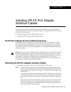
PA-FE-TX and PA-FE-FX Fast Ethernet 100BaseT Port Adapter Installation and Configuration
8-4
The individual interface port numbers always begin with 0. The number of additional ports depends
on the number of ports on a port adapter. For example, if the PA-FE in slot 4 (with the interface
address 4/0 [port adapter slot 4, and interface port 0]) were in slot 2, the port adapter’s interface
would be numbered 2/0.
Note For the Cisco 7206VXR and Cisco 7206 router shelves, the PA-FE in port adapter slot 4
would have the address x/4/0, where x is the number assigned to the router shelf during the initial
configuration of the Cisco AS5800 Universal Access Server.
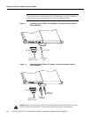
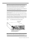
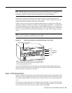
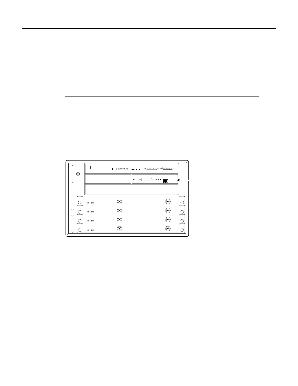
Figure 8-2 shows the port adapter slots and interface ports of a Cisco uBR7200 series router. For a
Cisco uBR7246, the port adapter slots are numbered 1 and 2 and for a Cisco uBR7223, the port
adapter slot in numbered 1. (Slot 0 is always reserved for the Fast Ethernet port on the I/O
controller—if present.) The individual interface port numbers always begin with 0. The number of
additional ports depends on the number of ports on a port adapter.
Figure 8-2 Cisco uBR7200 Series Fast Ethernet Interface Port Number
Example—Cisco uBR7246
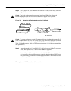
You can identify interface ports by physically checking the slot/interface port location on the front
of the router or by using show commands to display information about a specific interface or all
interfaces in the router.
VIP2 Ports
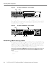
On the VIP2 installed in Cisco 7500 series or Cisco 7000 series routers, physical port addresses
specify the actual physical location of each interface port on the router interface processor end. (See
Figure 8-3.) However, when you move a VIP2 to a different slot, the first number in the address
changes to reflect the new chassis slot number. This address is composed of a three-part number in
the format chassis slot number/port adapter number/interface port number, as follows:
• The first number identifies the chassis slot in which the VIP2 is installed (as shown in the
example system in Figure 8-3).
• The second number identifies the physical port adapter number on the VIP2, either 0 or 1.
• The third number identifies the interface port on the PA-FE, which is always numbered as
interface 0.
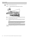
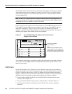
H11505
PA-FE-TX port adapter
(port number 2/0)
Note:
The Mll and RJ-45 interface ports on
the port adapter are both numbered as
interface port 0. Only one interface can
be used on each port adapter at a time.