


Receptacles, Cables, and Pinouts
PA-FE-TX and PA-FE-FX Fast Ethernet 100BaseT Port Adapter Installation and Configuration
1-6
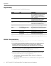
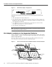
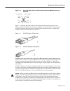
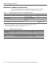
Figure 1-8 shows the RJ-45 cable connectors. Cisco Systems does not supply Category 5 UTP RJ-45
cables; these cables are available commercially. Table 1-1 lists the pinouts and signals for the
PA-FE-TX RJ-45 connectors.
Figure 1-8 PA-FE-TX RJ-45 Connections—Plug and Receptacle
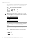
Warning
The ports labeled “Ethernet,” “10BaseT,” “Token Ring,” “Console,” and “AUX” are
safety extra-low voltage (SELV) circuits. SELV circuits should only be connected to other SELV
circuits. Because the BRI circuits are treated like telephone-network voltage, avoid connecting the
SELV circuit to the telephone network voltage (TNV) circuits.
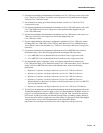
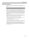
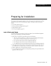
Table 1-1 PA-FE-TX RJ-45 Connector Pinout
Note Referring to the RJ-45 pinout in Table 1-1, proper common-mode line terminations should be
used for the unused Category 5, UTP cable pairs 4/5 and 7/8. Common-mode termination reduces
the contributions to electromagnetic interference (EMI) and susceptibility to common-mode
sources. Wire pairs 4/5 and 7/8 are actively terminated in the RJ-45, 100BaseTX port circuitry in the
PA-FE-TX.
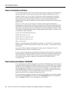
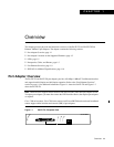
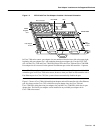
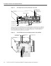
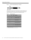
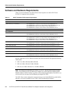
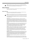
Depending on your RJ-45 interface cabling requirements, use the pinouts in Figure 1-9 and
Figure 1-10.
Figure 1-9 Straight-Through Cable Pinout—PA-FE-TX RJ-45 Connection to a Hub or
Repeater
Pin Description
1 Receive Data + (RxD+)
2 RxD–
3 Transmit Data + (TxD+)
6 TxD–
H2936
8 7 6 5 4 3 2 1
RJ-45 connector
Hub or repeaterFEIP
3 TxD+
6 TxD–
1 RxD+
2 RxD–
3 RxD+
6 RxD–
1 TxD+
2 TxD–
H3137