


Configuring PA-FE Port Adapter Interfaces 8-5
Note Although the processor slots in the seven-slot Cisco 7000 and Cisco 7507 and thirteen-slot
Cisco 7513 are vertically oriented and those in the five-slot Cisco 7010 and Cisco 7505 are
horizontally oriented, all models use the same method for slot and port numbering.
Interface ports on the VIP2 maintain the same address regardless of whether other interface
processors are installed or removed. However, when you move a VIP2 to a different slot, the first
number in the address changes to reflect the new slot number.
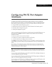
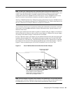
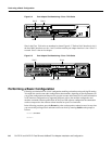
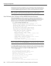
Figure 8-3 shows some of the slot port adapter and interface ports of a sample Cisco 7505 router.
The first port adapter slot number is 0, and the second port adapter slot number is 1. The individual
FE interface numbers arealways 0. For example, on theFE-equipped VIP2in slot 3 (see Figure 8-3),
the address of the FE interface is 3/0/0 (interface processor slot 3, port adapter slot 0, and interface
port 0). If a second PA-FE were installed in port adapter slot 1 on this VIP2, its address would be
3/1/0.
Note If you remove the PA-FE-equippedVIP2 (seeFigure 8-3) from slot 3 and install it in interface
processor slot 2, the address of this FE port becomes 2/0/0.
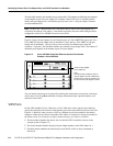
Figure 8-3 Fast Ethernet Interface Port Number Example—Cisco 7505
You can also identify interface ports by physically checking the slot/port adapter/interface port
location on the back of the router or by using software commands to display information about a
specific interface or all interfaces in the router.
Cisco 7100 Series Ports
In Cisco 7100 series routers, the slot number is the location in the chassis where the interface resides
and the portnumber isthe physical port. Interfaces in theCisco IOSsoftware areidentified bya type,
slot number, and port number. For example, serial 3/1 indicates port 1 on the serial port adapter in
slot 3.
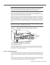
Slots in the Cisco 7120 series routers are numbered as shown in Figure 8-4. The fixed LAN interface
is slot 0, the fixed WAN interface is slot 1, and the modular port adapter interface is slot 3. On the
Cisco 7120 series slots 2 and 4 are not used. Slot 5 is the service adapter.
H5921
Slot 0
Slot 1
Slot 2
Slot 3
Interface
processor
slots
EJECT
SLOT 0
SLOT 1
NORMAL
CPU HALT
RESET
CONSOLE
ROUTE SWITCH PROCESSOR
AUX.
ENABLE
3/0/0 (PA-FE-TX port adapter)
Note: The MII and RJ-45 interface ports on the first port adapter
are both numbered as interface port 0. Only one interface can be
used on each port adapter at a time.