


2-5
Cisco SFS 7000P and SFS 7000D InfiniBand Server Switches Hardware Installation Guide
OL-10853-01
Chapter 2 Preparation for Installation
Power Requirements
Air Flow
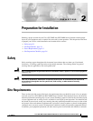
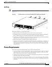
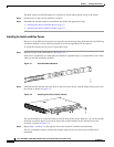
Note The air flows from front to back through the Cisco SFS 7000P and SFS 7000D Server Switches. (See
Figure 2-1.)
Figure 2-1 Air Flow Direction in the Cisco SFS 7000P and SFS 7000D Server Switches
Follow these guidelines to ensure proper airflow:
• Maintain ambient airflow throughout the data center to ensure normal operation.
• If installing in an enclosed cabinet, ensure that the cabinet has adequate ventilation, and allow at
least 2.5 inches (6.4 cm) of clearance between the chassis vents and the cabinet wall.
• If placing the switch adjacent to a device that exhausts air towards the switch, the horizontal distance
between the devices should be a minimum of 6 inches (15.2 cm).
• Ensure that cables do not obstruct the airflow through the chassis.
• Consider heat dissipation of all equipment when determining the air-conditioning requirements, as
specified in the hardware installation guide. When evaluating airflow requirements, consider that
hot air generated by equipment at the bottom of the rack can be drawn into the intake ports of the
equipment above.
Power Requirements
Follow these requirements when preparing your site for the switch installation:
• In systems configured with two power supplies, connect each of the two power supplies to a separate
input power source. If you fail to do this, your system might be susceptible to total power failure
due to a fault in the external wiring or a tripped circuit breaker.
• To prevent a loss of input power, be sure that the total maximum load on each source circuit is within
the current ratings of the wiring and breakers.
• The AC power receptacles used to plug in the chassis must be the grounding type. The grounding
conductors that connect to the receptacles should connect to protective earth ground at the service
equipment.
181224
Front
Back