


3-11
Cisco SFS 7000P and SFS 7000D InfiniBand Server Switches Hardware Installation Guide
OL-10853-01
Chapter 3 Installing the Switches
Connecting Network Devices
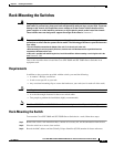
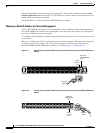
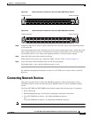
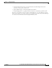
Figure 3-9 Power Connector Locations for the Cisco SFS 7000P Server Switch
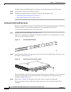
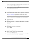
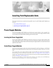
Figure 3-10 Power Connector Locations for the Cisco SFS 7000D Server Switch
Step 4
Connect the other end of each AC power cable into a 90-to 264-VAC power outlet operating between
47 Hz and 63 Hz.
The switch automatically starts and boots up. Use the correct external power source. Attach the switch
only to approved power sources, as indicated by the electrical ratings label. If you are unsure of the
correct power-source to use, contact your support personnel or your local power company.
Step 5 Check the LEDs on the front of the Server Switch.
When the device first powers up, it performs a POST. (See the “LEDs” section on page 5-1.)
Step 6 Log in and assign a network address after you see the login prompt.
The default login is: super, and the default password is: super.
For additional management information, see the Cisco SFS 7000 Series Product Family Command
Reference.
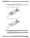
Connecting Network Devices
This section describes how to connect the InfiniBand switches to other network devices. These
InfiniBand switches can then be interconnected to InfiniBand devices such as InfiniBand-enabled
servers.
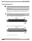
The Cisco SFS 7000P and SFS 7000D Server Switches support the following types of connectors:
• Serial console port
• Ethernet Management port—RJ-45 jack for unshielded twisted-pair connections
• Cisco SFS 7000P Server Switch—4x 10-Gbps InfiniBand connectors
and
Cisco SFS 7000D Server Switch—4x 10/20-Gbps InfiniBand connectors
Note There is a performance degradation if you mix 10-Gbps and 20-Gbps InfiniBand ports.
144945
Power connector Power connector
180601
Power connector
Power connector