


—20—
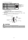
(1) Connector pin configuration
(2) Electric characteristics
1) Drive voltage: 24 VDC
2) Drive current: Approx. 1 A max. (not to exceed 510 ms.)
3) DRSW signal: Signal levels: “L” = 0 to 0.8 V, “H” = 2 to 3.3 V
(3) DRSW signal
DRSW signal status can be tested with the DLE+EOT, GS+a, or GS+r
command or at pin 34 on the parallel interface port.
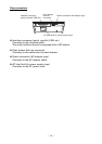
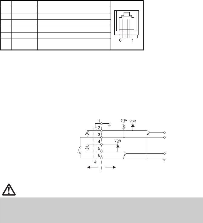
(4) Drive circuit
No. Signal Function
1 FG Frame ground Connector used:
TM5RJ3-66 (Hirose) or
equivalent
Applicable connector:
TM3P-66P (Hirose) or
equivalent
2 DRAWER1 Cash drawer 1 drive signal
3 DRSW Cash drawer switch input
4 VDR Cash drawer drive power supply
5 DRAWER2 Cash drawer 2 drive signal
6 GND Signal ground (common ground on
circuits)
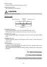
CAUTION
Cash drawers 1 and 2 cannot be operated at the same time.
The solenoid used for the cash drawer should be 24 Ω or more. Do not allow the
electric current to exceed 1 A. Excessive current could damage or burn out the
circuits.
Cash drawer kick-out connector
Cash drawer open/
close switch
Shielded
Cash drawer Printer