


iDP-3210 User’s Manual
34/67 CITIZEN
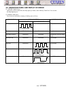
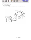
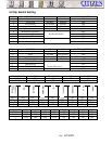
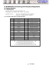
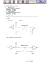
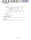
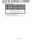
6.1.3 I/O SIGNALS
(1) Input Signals to the Printer
• DATA : 8-bit parallel signal (positive logic)
• STB : Strobe signal to read 8-bit data (negative logic)
• RESET : Signal to reset the entire printer (negative logic) 1m sec or more
(2) Output Signals from Printer
• ACK : An 8 bit data request signal. Pulse signal output at the end of the BUSY signal. (negative logic)
• BUSY : The signal to indicate BUSY state of the printer. Input new data for "LOW". (positive logic)
• FAULT : The signal which is made "LOW" when the printer is in alarm state. All the control circuits inside
the printer are stopped at this time.(negative logic)
• PE : The signal which is output when paper runs out or goes scarce. (positive logic)
• Drawer Switch Output: With the switch open, this signal goes "HIGH". When shorting, this goes "LOW".
(3) Power supply
• +5 V DC : This is 5V pulled up by a 3.3kΩ resistor.
• GND : This is the common ground for the circuit.
idp-3210 User's Manual