


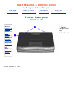
MAINTENANCE & SERVICE GUIDE
for Prosignia 150 Series Computer
Index Page Preface -or- Notice Specifications Battery Pack
Product Description Illustrated Parts Catalog Troubleshooting Removal & Replacement
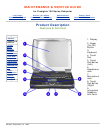
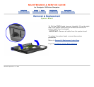
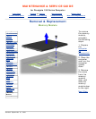
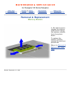
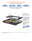
Removal & Replacement
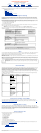
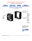
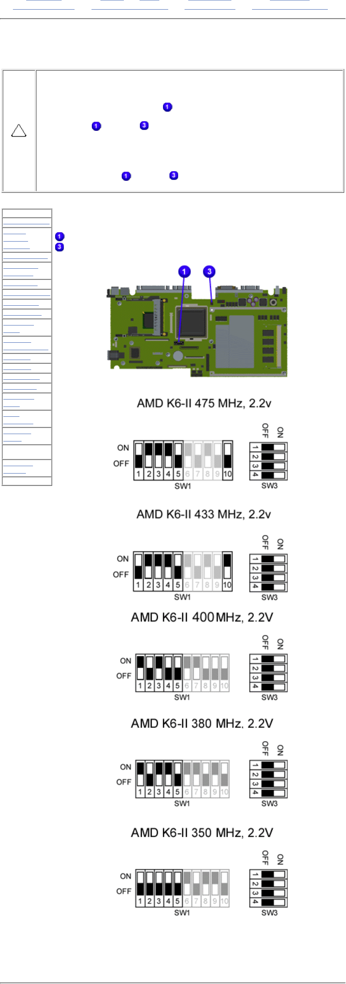
Processor Dipswitch Settings
If the system board dip switch voltage settings are not correct, damage may
occur to the computer and/or system board.
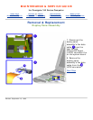
For the 350, 380, 400 & 475 MHz Processors:
only change settings 1-5 on SW1
. Settings 6-10 vary by model and should
not be changed when replacing the system board. Ensure the dip switch voltage
settings (SW1
and SW3 ) on the system board are correct for the computer
model and processor voltage marked on the processor chip.
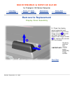
For the 433 MHz Processor:
You may change settings 1-5 as well as 10. Settings 6-9 vary by model and
should not be changed when replacing the system board. Ensure the dip switch
voltage settings (SW1 and SW3 ) on the system board are correct for the
computer model and processor voltage marked on the processor chip.
.
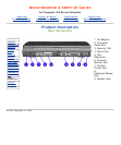
>Preliminaries
>Serial
Number
Location
>Battery Pack
>Touchpad
Assembly
>Keyboard
>Heatspreader
>Processor
>Hard Drive
>CD/DVD
Drive
>Battery
Charger Board
>Modem
>Display
>CPU cover
>Speakers
>Diskette
Drive
>Fan
Assembly
>System
Board
>Dipswitch
Settings
>Memory
Module
.
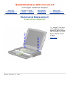
NOTE:
The black area on the dip switch indicates the position of the
switch.
Switch 1
Switch 3
Revised: September 16, 1999