


MAINTENANCE & SERVICE GUIDE
for Prosignia 150 Series Computer
Index Page Preface -or- Notice Specifications Battery Pack
Product Description Illustrated Parts Catalog Troubleshooting Removal & Replacement
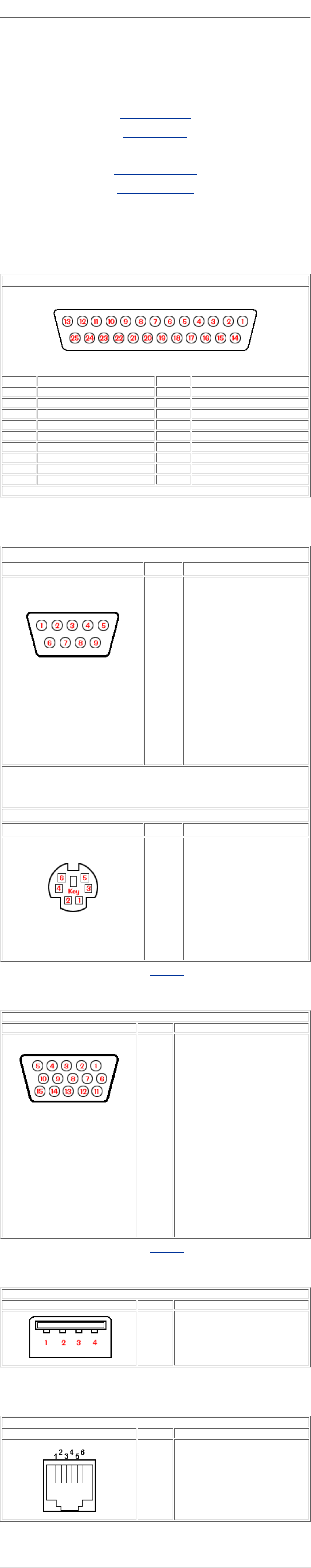
Connector Pin Assignments
This appendix provides connector pin assignment tables for Compaq Compaq
Prosignia 150 Portable Computers. For more information on connectors, refer
to the section on Rear Connectors.
Click on a link:
Parallel Connector
Serial Connector
Keyboard/Mouse
External VGA Monitor
Universal Serial Bus
Modem
NOTE: The signals in all tables of this appendix are considered active high unless
otherwise indicated by an asterisk (*).
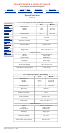
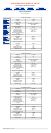
Parallel Connector
Pin Signal Pin Signal
1 Strobe* 10 Acknowledge*
2 Data Bit 0 11 Busy
3 Data Bit 1 12 Paper Out
4 Data Bit 2 13 Select
5 Data Bit 3 14 Auto Linefeed*
6 Data Bit 4 15 Error*
7 Data Bit 5 16 Initialize Printer*
8 Data Bit 6 17 Select In*
9 Data Bit 7 18-25 Signal Ground
* = Active low
Return to the top.
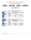
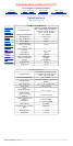
Serial Connector
Connector Pin Signal
1
2
3
4
5
6
7
8
9
Carrier Detect
Receive Data
Transmit Data
Data Terminal Ready
Signal Ground
Data Set Ready
Ready to Send
Clear to Send
Ring Indicator
Return to the top.
Keyboard/Mouse
Connector Pin Signal
1
2
3
4
5
6
Data 1
Data 2
Ground
+5 V
Clock 1
Clock 2
Return to the top.
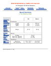
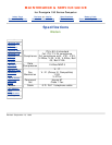
External VGA Monitor
Connector Pin Signal
1
2
3
4
5
6
7
8
9
10
11
12
13
14
15
Red Analog
Green Analog
Blue Analog
Not connected
Ground
Ground Analog
Ground Analog
Ground Analog
Not connected
Ground
Monitor Detect
DDC2B Data
Horizontal Sync
Vertical Sync
DDC2B Clock
Return to the top.
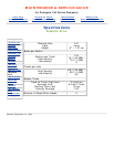
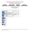
Universal Serial Bus
Connector Pin Signal
1
2
3
4
+5V
Data -
Data +
Ground
Return to the top.
Modem
Connector Pin Signal
1
2
3
4
5
6
Unused
Unused
Tip
Ring
Unused
Unused
Return to the top.
Revised: September 16, 1999