


. . . . . . . . . . . . . . . . . . . . . . . . . . . . . . . . . . . . .
5-2 Removal and Replacement Procedures
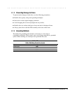
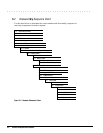
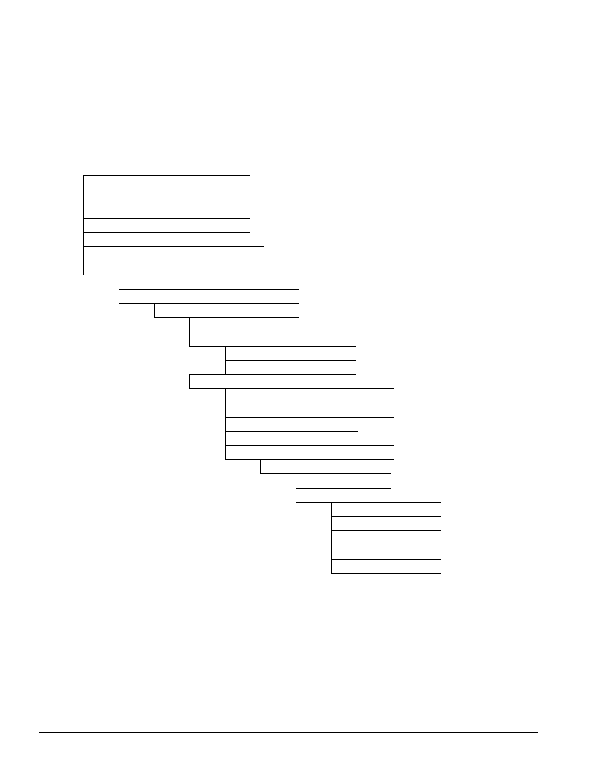
5.2 Disassembly Sequence Chart
Use the chart below to determine the section number and disassembly sequence for
removing components from the computer.
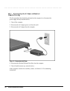
5.3.1 Disconnect AC Power
5.3.1 Disconnect External Diskette Drive Bay
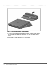
5.3.2 Undock the Computer
5.3.7 PC Card
5.4.1 Computer Logo
5.4.2 Computer Feet
5.3.3 Remove Handle Battery Pack
5.4.3 Handle
5.3.4 Remove DualBay Device (Optional Battery)
5.3.5 Pointing Device
5.3.6 Hard Drive
5.5.1 Memory Cover
5.5.2 Memory Board
5.5.3 Lithium Clock Battery
5.5.4 CPU Base Cover
5.5.5 Processor Shield and Board
5.5.6 CPU Cover/Keyboard
5.9.1 Upper PCMCIA Door
5.9.5 PCMCIA Buttons
5.6 Display Assembly
5.7.1 Clutch Cover
5.7.2 Clutch
5.8.1 System Board
5.8.2 Heat Sink
5.9.2 Lower PCMCIA Door
5.9.3 DualBay Eject Button
5.9.4 PCMCIA
5.9.6 Display Ground Bracket
Figure 5-2
. Computer Disassembly Chart