


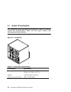
GS160/320 System Overview 2-5
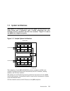
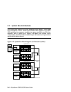
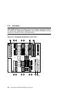
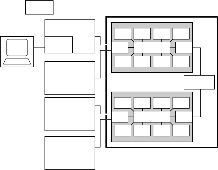
The switch on the backplane connects the CPU modules, memory modules, I/O
riser modules, and global port. In an 8-P system, the global ports connect the
QBBs to the distribution board. In a 16-P or a 32-P system, the global ports
connect the QBBs to the hierarchical switch.
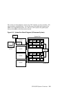
Figure 2–3 System Box Block Diagram (8-Processor System)
Modem
Operator
Console
PCI Box
Standard
I/O SCM
PCI Box
System Box
CPU
MEM
I/O GP
CPU CPU CPU
Switch
MEMMEMMEM
Distribution
Board
CPU
MEM
I/O GP
CPU CPU CPU
Switch
MEMMEMMEM
PCI Box
PCI Box
PK-0601-98