viii
Glossary
Index
Examples
6–1 SCM Power-Up Display ........................................................................6-2
6–2 SRM Power-Up Display ........................................................................6-6
6–3 Booting Tru64 UNIX from a Local SCSI Disk .................................... 6-16
6–4 RIS Boot .............................................................................................. 6-18
6–5 Tru64 UNIX Installation Display ....................................................... 6-20
6–6 Booting OpenVMS from a Local Disk ................................................. 6-22
6–7 InfoServer Boot ................................................................................... 6-24
6–8 OpenVMS Installation Menu.............................................................. 6-26
7–1 Set Ocp_Text Command...................................................................... 7-6
7–2 Show Boot*............................................................................................ 7-7
7–3 Show Config ..........................................................................................7-8
7–4 Show Device ........................................................................................ 7-16
7–5 Show Memory...................................................................................... 7-18
7–6 Defining Soft Partitions ...................................................................... 7-24
7–7 Defining Hard Partitions .................................................................... 7-26
8–1 Dial-In Configuration.......................................................................... 8-24
8–2 Alert Dial-Out Configuration.............................................................. 8-26
Figures
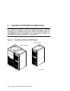
1–1 AlphaServer GS160 and GS80 Systems................................................ 1-2
1–2 Sample System Architecture................................................................. 1-5
2–1 System Box............................................................................................ 2-2
2–2 System Box Block Diagram (16-Processor System) .............................. 2-4
2–3 System Box Block Diagram (8-Processor System) ................................2-5
2–4 System Box QBBs (Top View)............................................................... 2-6
2–5 Backplane (System Box, Front View)....................................................2-8
2–6 CPU Module........................................................................................ 2-10
2–7 Memory Module .................................................................................. 2-11
2–8 Directory Module................................................................................. 2-12
2–9 Power Modules.................................................................................... 2-13
2–10 Power System Manager Module.......................................................... 2-14
2–11 Clock Splitter Module ......................................................................... 2-15
2–12 I/O Riser Module ................................................................................. 2-16


