Booting and Installing an Operating System 6-5
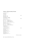
Example 6–1 SCM Power-Up Display (Continued)
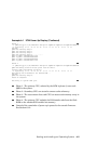
Phase 3
~I~ QbbConf(gp/io/c/m)=fbbfffff Assign=ff SQbb0=00 PQbb=00 SoftQbbId=fedcba98
~I~ SysConfig: 37 13 07 19 07 12 c7 13 37 13 f7 11 f7 13 37 13
SCM_E0>
QBB0 now Testing Step-D
QBB1 now Testing Step-D
QBB2 now Testing Step-D
QBB3 now Testing Step-D.............
QBB0 IO_MAP0: 000000C101311133
QBB1 IO_MAP1: 0000000000000003
QBB2 IO_MAP2: 0000000000000003
QBB3 IO_MAP3: 000000C001311133
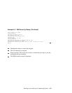
Phase 4
~I~ QbbConf(gp/io/c/m)=fbbfffff Assign=ff SQbb0=00 PQbb=00 SoftQbbId=fedcba98
QBB0 unloading console across port0 from PCI Box-1
Console COM1 from master PCI Box-0
~I~ SysConfig: 37 13 07 19 07 12 c7 13 37 13 f7 11 f7 13 37 13
Retrieving FRU information for Shared RAM...
SCM_E0>
QBB0 now Testing Step-E..
Power On Complete
Returning to system COM1 port
Phase 1. The primary CPU, selected by the SCM in phase 0, tests each
QBB in the system.
Phase 2. Secondary CPUs are tested to ensure cache coherency.
Phase 3. The tests ensure that each CPU can access each memory array in
the system.
Phase 4. The primary CPU unloads the PAL/console code from the flash
ROM on the standard I/O module into memory.
Control of the remainder of power-up is passed to the console firmware.
See Section 6.1.2.


