


5–40 Maintenance and Service Guide
Removal and Replacement Procedures
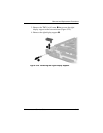
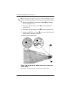
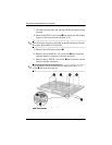
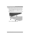
7. Turn the base enclosure top side up with the rear panel facing
forward.
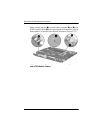
8. Remove the TM2.0 × 6.0 screw
1
that secures the left display
support to the base enclosure (Figure 5-31).
✎
The left display support is included in the Miscellaneous Plastics
Kit (spare part number 231454-001).
9. Remove the left display support
2
.
10. Remove the two HM5.0 × 9.0 screwlocks
3
that secure the
external monitor connector to the base enclosure.
11. Remove the six TM2.0 × 4.0 screws
4
that secure the system
board to the base enclosure.
✎
Evo Notebook N410c models have an additional TM2.0 × 3.5
screw
5
that must be removed.
Figure 5-31. Removing the System Board Screws
and Screwlocks