


5–44 Maintenance and Service Guide
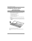
Removal and Replacement Procedures
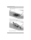
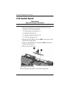
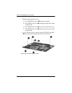
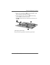
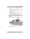
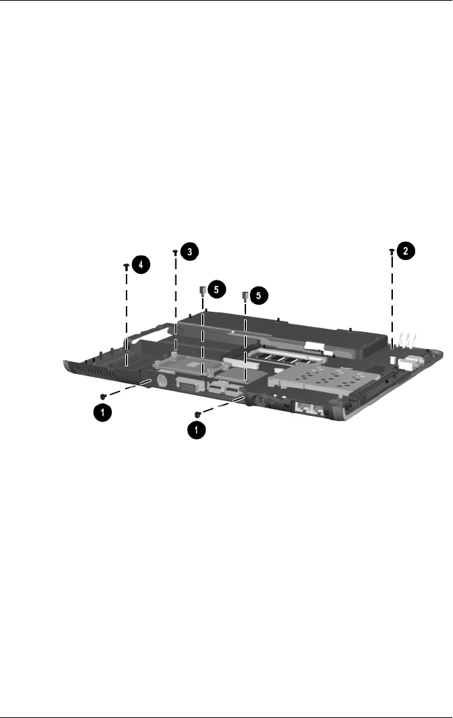
3. Remove the following screws:
❏ Two T8M2.0×6.0 screws 1 from the rear panel
❏ One T8M2.0×4.0 screw 2 in the upper right corner of the
system board
❏ One T8M2.0×4.0 screw 3 in front of the hard drive bay
❏ One T8M2.0×4.0 screw 4 in the lower left corner of the
system board
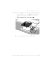
4. Use a 5.0-mm socket to remove the two M2.0×9.0 standoffs
5 that secure the system board to the base enclosure.
Removing the System Board Screws