


Removal and Replacement Procedures
Maintenance and Service Guide 5–3
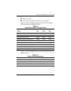
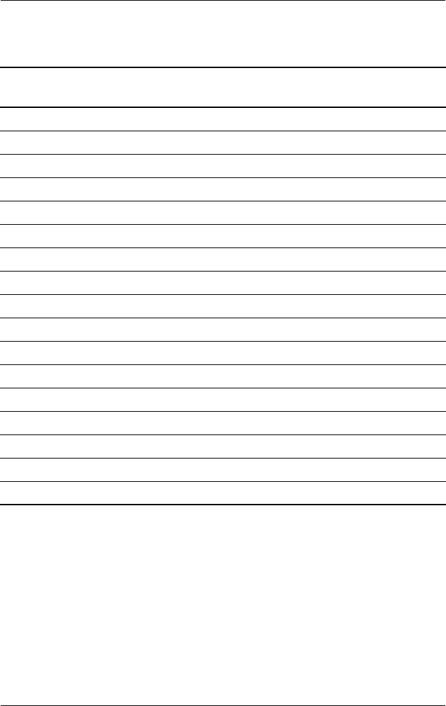
Section Description
# of Screws
Removed
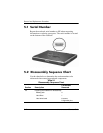
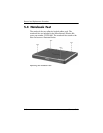
5.4 Notebook feet 0
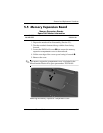
5.5 Memory expansion board 1 loosened
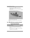
5.6 Mini PCI communications board 1 loosened
5.7 LED switch cover 2
5.8 Keyboard 1
5.9 Fan 3
5.10 Heat sink and fan 2 loosened, 4 removed
5.11 Processor 0
5.12 Display assembly 4
5.13 Top cover 13
5.14 Bluetooth wireless device 0
5.15 TouchPad 2
5.16 RTC battery 0
5.17 Speaker/microphone 2
5.18 Switch board 2
5.19 System board 5 screws, 2 standoffs
5.20 Modem board 2
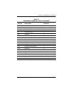
Table 5-1
Disassembly Sequence Chart
(Continued)