


Connect Tech Blue Heat/Net Sync User Manual
50 Revision 0.03
Memory Map of IUSC and PLD Functions
ColdFire (5272) Bus:
A ColdFire CS# signal is used to select the entire region, setup with the following attributes…
8K (8192) byte region
16 Bit bus
Use TA# signal to terminate the bus cycle (this places wait state generation in the hands of
the PLD logic).
o CSBR.EBI = 00b selects 16/32 SRAM/ROM mode
o CSBR.BW = 10b selects 16 bit bus
o CSOR.WS = 0x1F selects the use of the TA# signal
o CSOR.BAM = as required selects size of region
o CSOR.BA = as required sets 32 bit Base address of the region
o
ColdFire Bus Addresses A0 through A12 are used to “address” all items
A[12] divides the region into 2 (4096 byte) areas
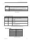
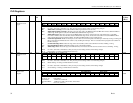
IUSC Access:
A[12] Must be zero (0).
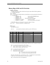
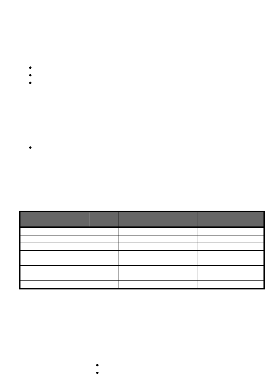
A[11..9] Are decoded into 8 functions which access the 4 IUSC devices
A11
A10
A9
IUSC
selected
Function
Notes
0
0
0
0
Register Read/Write
0
0
1
0
Interrupt Acknowledge
Write not allowed [1]
0
1
0
1
Register Read/Write
0
1
1
1
Interrupt Acknowledge
Write not allowed [1]
1
0
0
2
Register Read/Write
1
0
1
2
Interrupt Acknowledge
Write not allowed [1]
1
1
0
3
Register Read/Write
1
1
1
3
Interrupt Acknowledge
Write not allowed [1]
[1] A write to these addresses are ignored, but the ColdFire bus cycle is properly terminated.
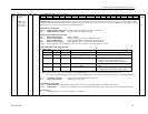
A[8] Is “connected” (inverted) to the IUSC S//D pin
0 = Selects “Serial Controller” registers in the IUSC device.
1 = Selects “DMA” registers in the IUSC device.
A[7] Is “connected” to the IUSC D//C pin
0 = Selects Serial “Control” registers
1 = Selects Serial “Data” registers
A write places data into the Transmitter FIFO
A read removes data from the Receiver FIFO
The word “connected” above, is used loosely to mean… The address bit is routed from the
ColdFire bus to the indicated IUSC pin via the logic in the PLD.
A[6] Is not used (set to zero for all operations).