


Connect Tech Blue Heat/Net Sync User Manual
Revision 0.03 51
A[5..1] Addresses IUSC registers (see Memory Map Table below).
A[0] Not used explicitly, A0 (along with BS0# and BS1#) select byte size portions of IUSC
registers.
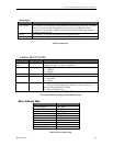
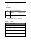
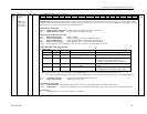
PLD Resource Access:
A[12] Must be one (1).
A[11..5] Are not used.
A[4..2] Are decoded into selections of internal PLD “registers”.
A4
A3
A2
Function
Notes
0
0
0
Real Time Clock
32 bit read/write (16 bit portions
also accessible)
0
0
1
LED Control
16 bit read/write only
0
1
0
Port-1 Line I/F control
16 bit read/write only
0
1
1
Port-2 Line I/F control
16 bit read/write only
1
0
0
Port-3 Line I/F control
16 bit read/write only
1
0
1
Port-4 Line I/F control
16 bit read/write only
1
1
0
Control
16 bit read/write only
1
1
1
Status
16 bit read only
A[1] Is used to select the 16 bit portions of the Real Time Clock register.
A[0] Is not used.
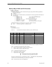
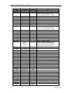
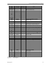
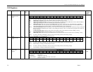
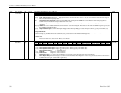
PLD Memory Map Table
Address
Offset
(in hex)
Area (item)
Accessed
Register
Accessed
Notes
IUSC Area
IUSC-0
000
IUSC-0 Sreg [1]
CCAR
002
IUSC-0 Sreg
CMR
004
IUSC-0 Sreg
CCSR
006
IUSC-0 Sreg
CCR
008
IUSC-0 Sreg
PSR
00A
IUSC-0 Sreg
PCR
00C
IUSC-0 Sreg
TMDR
00E
IUSC-0 Sreg
TMCR
010
IUSC-0 Sreg
CMCR
012
IUSC-0 Sreg
HCR
014
IUSC-0 Sreg
IVR
016
IUSC-0 Sreg
IOCR
018
IUSC-0 Sreg
ICR
01A
IUSC-0 Sreg
DCCR
01C
IUSC-0 Sreg
MISR
01E
IUSC-0 Sreg
SICR
020
IUSC-0 Sreg
RDR(TDR)
8/16 bit Serial Data (byte/word)