


4.0 THEORY OF OPERATION
4.1 OVERVIEW
The DP8 and DP9 Printers handle a large variety of documents. The two printers are identical
except that the DP9 is 3.2” wider. The mechanism consists of a printhead, a carriage drive
assembly and a document drive assembly. The electronics consist of a switching power
supply, a Main PCB, a sensor PCB and a keypad/display assembly.
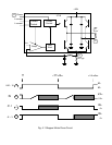
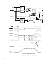
4.1.1 Carriage Drive Assembly
The carriage drive assembly positions the printhead as it prints each line of characters. The
printhead is mounted on a moveable carriage that is supported by a carriage shaft. The
carriage shaft is mounted to two pivot arms that allow the carriage to lift away from the platen
and accommodate different thickness documents. The printhead is held against the document
by the carriage shaft weight and springs. The carriage is lifted by a roller that rides across the
document surface and maintains a constant printhead to document gap, thereby maintaining
print quality across a wide document thickness range. An upper shaft stops the carriage from
rotating around the carriage shaft.
A toothed belt clamped to the carriage is driven by a pulley mounted on the carriage stepper
motor located on the left side of the metal box. The stepper motor moves the printhead in
1/120th of an inch increments along the print line. Position information is updated when the
carriage is detected by an optical sensor on the Sensor PCB.
The ribbon cartridge is driven by a shaft which is in turn driven from the carriage motor shaft
through a gear train which pivots so that the ribbon drive shaft rotates clockwise regardless of
the direction of carriage motor rotation. The entire carriage drive assembly lifts away from the
document drive and the ribbon shield and ribbon guides mounted to the carriage lower away
from the printhead for easy access to the ribbon path when replacing cartridges.
4.1.2 Document Drive Assembly
The document drive assembly positions inserted documents. The document drive stepper
motor mounted on the right side of the document drive is connected to the two drive rollers
through toothed belts. A pinch roller is spring loaded against each drive roller providing friction
feed for documents of varying thickness. Documents are fed between the drive and pinch
rollers, with the spring-loaded pinch roller automatically adjusting to the document thickness.
The stepper motor positions in 1/120th of an inch increments.
The presence of a document in the input tray is sensed by the frontmost of four optical sensors
located above the document path. When auto alignment is active a gate is raised across the
document path during document insertion. At that time the printhead moves past its normal left
home position, activating an arm that raises the gate. The rising gate reduces the spring
loading force on the front document drive rollers, allowing documents to rotate and align
against the gate. Three optical sensors in line behind the front rollers check the leading
document edge to insure that it is sensed within a programmable alignment tolerance. These
sensors are also used to position the top or bottom edge of the document relative to the
printhead. After alignment is verified, the printhead moves to the right, lowering the gate out of
the document path and restoring normal loading force to the document drive rollers.
4.1.3 Switching Power Supply
The switching power supply is mounted to the inner front surface of the metal box. AC line
voltage is wired through a power switch to the power supply. The power supply provides
regulated +38VDC to the Main Printed Circuit Board.
21