4.1.4 Main Printed Circuit Board
The Main PCB is located in the rear of the printer and contains power supply, control and
driver electronics. The regulated +38VDC is converted to +5VDC, +12VDC and –12VDC by a
switching regulator on the main PCB. The +38VDC drives the printhead and stepper motors.
The control electronics are based on a 68HC12 microcontroller, a 128 Kbyte flash memory and
32Kbyte RAM. The microcontroller contains a 16-bit microprocessor, non-volatile EEPROM,
timers, serial I/O communication ports and baud rate generator, multiple parallel ports and an
A/D converter driven by the optical sensors. The main PCB also contains circuitry for
interfacing to the keyboard/display assembly, driving the printhead and stepper motors and
providing signal level conversion for the serial interface signals. The driver electronics include
switching transistors that drive the printhead and 4 H-Bridge switching regulators that drive the
carriage and document drive stepper motors. An optical sensor mounted on the main PCB
detects opening of the cabinet.
4.1.5 Keypad/Display Assembly
The keyboard/display assembly consists of a 16 key keypad arranged in a 8 x 2 scanning
matrix and a 2 line by 16 character dot matrix LCD display module. The display buffers 32
characters of data and generates the dot patterns and timing to drive the LCD.
4.2 ELECTRONICS IN DETAIL - Refer to #72135 Schematic
4.2.1 Low Voltage Supplies
The +38VDC supplied from the switching power supply is converted to +5VDC, +12VDC and –
12VDC by switching regulator V1 (or alternate V2) using Schottky diode D31 and a small cube
switching transformer. The 100KHz switching frequency is set by C19 & R38. The +5VDC is
monitored by Q3 so that the electronics are held reset if the +5VDC is not stable.
4.2.2 Microprocessor System
The 68HC12 microcontroller U10 has a 250 nanosecond cycle time that it generates from
16Mhz crystal Y1. Each cycle the 68HC12 provides a timing pulse on TP1 for synchronizing
the devices on the data bus and updates the address on pins A0-A18. The high order address
lines are decoded by the 68HC12 to generate chip selects to the RAM and flash memory.
The 32 KByte RAM U9 is selected by U9 pin 20. The RAM provides workspace and buffer
memory for the 68HC12. All printer, communication and service configuration parameters are
stored in EEPROM internal to the 68HC12. The128 KByte flash memory U8 is selected by U8
pin 22. This memory contains the dot patterns for all printable characters and all programs that
the 68HC12 executes to control the printer.
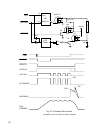
4.2.3 Stepper Motor Drivers
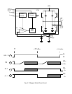
Each stepper motor has 2 stator coils, each driven by a 3718 driver U1, 2, 6 and 7. Each 3718
contains 4 transistors arranged in a H-Bridge that can apply +38 VDC to either end of the coil,
a 25KHz switching oscillator and comparators that limit the coil current by sensing the voltage
on an external resistor R4, 6, 29 or 32. Each 3718 is controlled by 3 signals driven from the
68HC12: a phase signal which indicates which direction current is to flow through the coil and
two signals which limit the current to 0, 20, 60 or 100% of a maximum value determined by the
external resistor. 0% is used to turn off a winding, 20% is used when the motor is holding a
fixed position and 60 or 100% is used when the motor is rotating. See Figure 4-1 for typical
voltage waveforms on both ends of a motor coil and the external resistor. The ground plane
under the 4 3718's is connected to the rear panel heat sink to reduce the temperature rise.
22


