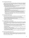
5.4.2 Carriage Drive Belt Tension
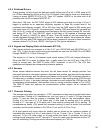
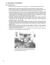
The carriage belt connects the carriage drive motor to the carriage. Incorrect carriage belt
tension can cause uneven character width and spacing, poor bi-directional print alignment,
stalling and premature belt wear. Tension is adjusted with the screw fastening the carriage belt
idler pulley bracket to the right box flange.
1. Loosen the adjustment screw until the upper belt run can be pushed down against the lower
belt run at the center of the printer with about 1 lb. (400g) of force.
2.a. Procedure for firmware ‘E9' and earlier (see 3.7)
Use 955 FUNCT to print 4 lines of H’s. Increase the belt tension by turning the adjustment
screw 1/2 turn clockwise and press ENTER to print 4 more lines. Adjust belt tension and
print as required. Select the loosest belt tension that gives good alignment of characters. If
no setting gives good alignment, adjust the CAR ALIGN parameter (see 5.2) and then
repeat this procedure.
b. Procedure for printers with firmware ‘EA’ and later (see 3.7)
Use 943 function to print 6 lines of double-high double-wide zeros and select the best line
of aligned characters. If none are desirable, increase the belt tension by turning the
adjustment screw 1/2 turn clockwise and print using 943 FUNCT again. Select the loosest
belt tension that gives good alignment of zeros. Press 94 FUNCT and ENTER 4 times.
The display will read “CAR. ALIGN =” Use A↑ or B↓ to enter the value printed at the end
of the selected line of printed zeros.
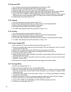
5.4.3 Document Drive Belt Tension
The document drive belt connects the document motor to the rear document roller. Incorrect
document belt tension causes uneven line spacing and document drive stalling.
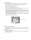
1. Use a spring gauge to deflect the center of the document drive belt. Adjust only if an 8 oz.
(225 gm.) force deflects the belt less than 0.02” (0.5 mm) or more than 0.04” (1 mm).
2. Loosen the 4 screws that fasten the document drive motor.
3. Move the motor toward or away from the rear document drive roller to adjust the tension and
tighten the screws. Repeat step 1.
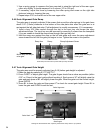
5.4.4 Carriage Shaft Cam and Shaft Rack
The carriage shaft cam sets the carriage shaft height so that the gap wheel rises very slightly
when the carriage moves onto the right platen end. Light printing can occur if the carriage shaft
is too high. Document snagging or irregular movement of wide documents can occur if the
shaft is too low.
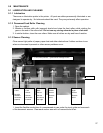
1. Move the carriage to the printer center and raise the carriage while holding the box down.
2. If both carriage shaft ends don’t touch the top of the slots in the box flanges, reposition the
shaft by pushing the higher shaft end down while raising the lower shaft end.
3. Check that the rubber wheel is in firm contact with the platen when the carriage is at the left
and right platen ends.
4. Check that the carriage rises about 0.010 (0.25mm) as the carriage moves from its
rightmost position onto the right platen end.
5. If this does not occur, loosen the shaft cam screw on the right box flange and rotate the
cam. Hold the cam with a small screwdriver blade in the rectangular slot when tightening the
screw to stop the cam from rotating.
6. Do a test print to insure that print darkness does not vary between the left and right sides.
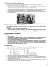
5.4.5 Rear Document Roller Spring Force
The rear document roller springs are formed wires that pull the rear upper document rollers
against the lower rollers. The springs are adjusted by raising or lowering the cams mounted on
the front screws fastening the side plates to the platen. Incorrect spring force can cause
document skewing, slipping or stalling.
33


