5.5.3 Sensor PCB
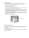
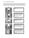
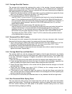
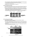
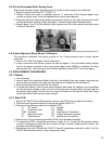
1. Turn off power and disconnect the flex cable from the sensor PCB.
3. Remove the two nuts fastening the PCB to the input guide.
4. Raise the upper front roller and remove the PCB by pushing it to the rear.
5. Install the lower (thick) sensor insulator, the new PCB and the upper (thin) sensor insulator.
6. Push the PCB and insulators forward, fasten the nuts and reconnect the flex cable.
7. Adjust TOP, LEFT OFFSET, LEFT MARGIN and EJECT HOLD parameters so that inserted
documents are correctly positioned (See 5.2). Record new values on the parameter label.
8. Calibrate the skew sensor (See 5.4.9).
5.5.4 Keypad
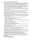
1. Turn off power and remove the cabinet (See 5.5.1).
2. Place the mechanism upside down so it rests on the box and keypad bracket.
3. Remove the nuts fastening the keypad to the bracket.
4. Disconnect the flex cable and remove the keypad.
5. To install a new keypad reverse the procedure in steps 1 to 4
5.5.5 Display
1. Turn off power and remove the cabinet (See 5.5.1).
2. Place the mechanism upside down so it rests on the box and keypad bracket.
3. Remove the nuts fastening the display to the bracket.
4. Pull the flex cable connector cover away from the connector to disconnect the flex cable.
5. To install a new display reverse the procedure in steps 1 to 4
5.5.6 Power Supply PCB
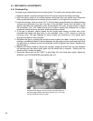
1. Disconnect the AC power cord and remove the cabinet (see 5.5.1)
2. Raise the insulator flap covering the Power Supply PCB and disconnect the AC and DC
connectors from the PCB.
3. Remove the 4 screws fastening the PCB to the box and remove the PCB.
4. Position the mechanism so that it rests on the keypad bracket and input tray.
5. Put the screws into the new PCB.
6. Insure that the insulator stays located around each mounting boss while mounting the new
PCB and fasten the screws.
7. Reconnect the AC and DC connectors (the AC connector mounts to the end of the header
labeled “L” on the PCB).
8. Insure that the insulator flap separates the power supply from the flex cables.
5.5.7 Carriage Motor
1. Remove the cabinet (see 5.5.1).
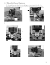
2. Disconnect the carriage motor from J5 of the Main PCB.
3. Remove 3 screws from the motor (shaft side) that fasten it to the box. Guide the carriage
belt off the motor pulley (do not loosen the belt tensioner or you will have to readjust it) and
remove the motor.
4. Transfer the motor pulley to the new motor. Leave a .01" (0.2mm) gap between the pulley
hub and the motor flange.
5. Install the new motor in the box, onto the carriage drive belt, and fasten with the 3 screws.
6. Connect the motor to J5 on the Main PCB and replace the cabinet.
7. Set the LEFT HOME, LEFT MARGIN and CAR ALIGN parameters (see 5.2).
8. Tension the carriage belt (see 5.4.2).
36


