


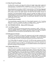
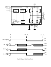

4.2.4 Printhead Drivers
During printing, 24 bits of print dot data are serially shifted into U3 to U5. A FIRE pulse at U5
pin 12 then transfers the 24 bits to the U3 to U5 outputs. Each high bit turns on a printwire by
turning on power MOSFETS Q10 to 33. Timer U13 applies +38VDC to the other side of all
printwire coils via Q5 and power MOSFET Q7.
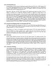
After about 100 usec. the NO CHOP signal at D35 cathode goes high and timer U13 pin 3
begins to oscillate as an open-loop switching regulator to keep the current level in the
printhead coils relatively constant. 100 to 200 usec. later the FIRE signal at D34 anode goes
high which turns off U13 and Q7. On pre-revision F boards, FIRE also cleared the printwire bits
from U3 to U5, turning off all transistors and discharging the coil current through D6, the coils,
and diodes D7 to 30. The FIRE-EXT signal at the base of Q4 enabled a discharge path
through Q8 back to +38VDC for about 40 usec. Then Q8 turned off and the remaining coil
current dissipated through Q10 to 33. On revision F and later boards, the printwire bits remain
set until 320 usec after FIRE began and Q8 has been jumpered to provide a direct connection
between diodes D7 to 30 and +38VDC. See Figure 4-2 for typical waveforms.
4.2.5 Keypad and Display (Refer to Schematic #72135)
The keypad switches are arranged in a 8 by 2 X-Y grid. KEYSCAN0 and KEYSCAN1 at J11
pins 12 & 11 drive the grid rows and the grid columns are read into the 68HC12 on KEYBD0
through KEYBD7 at J11 pins 3 through 10.
The display is a 2 line by 16-character liquid crystal display (LCD) with integral electronics.
When the 68HC12 is ready to display data, it reads status from the LCD and if the LCD is
ready to accept data, the 68HC12 writes ASCII characters to the LCD. The LCD then
generates and displays the corresponding character patterns.
4.2.6 Sensors
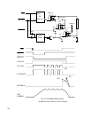
Seven optical reflective sensors are used: the left home sensor for carriage position, four
document sensors for document presence, alignment and position, one document edge sensor
located on the carriage, and the cabinet open sensor on the main PCB. All sensors operate in
the same way: a constant current is provided to the sensor’s light emitting diode (LED) through
a resistor to +5 volts. If an object (carriage, document or cover) reflects the LED light onto the
corresponding phototransistor, the transistor turns on, raising its emitter voltage to 2 to 4 VDC.
The 68HC12 reads and digitizes the phototransistor emitter outputs via an internal A/D
converter.
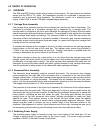
4.2.7 Character Printing
The carriage motor steps the carriage in 1/120" increments but dots can be printed three times
per increment. Printing at 10 characters per inch (cpi) uses a 13 wide X 23 high character
matrix. 13 dots are used for printing a character and 5 dots for the intercharacter space.
Printing at 12 cpi uses a 11 X 23 matrix with 11 dots used for printing and 4 for spacing.
Printing at 17.1 cpi uses a 7 X 23 matrix with 7 dots used for printing and 3.5 for spacing. At
correspondence quality (CQ) speed half increment printing is used to double the horizontal
resolution and the matrix doubles to 25 X 23 for 10 cpi and 19 X 23 for 12 cpi.
At all print speeds only every other dot position can be printed so the maximum number of
horizontal dots printed is 4 for a 7 wide matrix, 6 for an 11 wide, 7 for a 13 wide, 10 for a 19
wide and 13 for a 25 wide matrix. In all print modes the upper 19 printwires are used for
printing normal characters, the 20
th
through 23
rd
wires for lower case descenders and the 24
th
wire for underlining. Printing occurs at a maximum frequency of 1,350 Hz.
25