Ultra37000 CPLD Family
Document #: 38-03007 Rev. *E Page 14 of 64
5.0V Device Characteristics
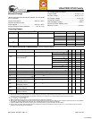
Maximum Ratings
(Above which the useful life may be impaired. For user guide-
lines, not tested.)
Storage Temperature .................................–65°C to +150°C
Ambient Temperature with
Power Applied.............................................–55°C to +125°C
Supply Voltage to Ground Potential............... –0.5V to +7.0V
DC Voltage Applied to Outputs
in High-Z State................................................–0.5V to +7.0V
DC Input Voltage ............................................–0.5V to +7.0V
DC Program Voltage.............................................4.5 to 5.5V
Current into Outputs ....................................................16 mA
Static Discharge Voltage...........................................> 2001V
(per MIL-STD-883, Method 3015)
Latch-up Current.....................................................> 200 mA
Operating Range
[2]
Range Ambient Temperature
[2]
Junction Temperature Output Condition V
CC
V
CCO
Commercial 0°C to +70°C 0°C to +90°C 5V 5V ± 0.25V 5V ± 0.25V
3.3V 5V ± 0.25V 3.3V ± 0.3V
Industrial –40°C to +85°C –40°C to +105°C 5V 5V ± 0.5V 5V ± 0.5V
3.3V 5V ± 0.5V 3.3V ± 0.3V
Military
[3]
–55°C to +125°C –55°C to +130°C 5V 5V ± 0.5V 5V ± 0.5V
3.3V 5V ± 0.5V 3.3V ± 0.3V
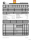
5.0V Device Electrical Characteristics Over the Operating Range
Parameter Description Test Conditions Min. Typ. Max. Unit
V
OH
Output HIGH Voltage V
CC
= Min. I
OH
= –3.2 mA (Com’l/Ind)
[4]
2.4 V
I
OH
= –2.0 mA (Mil)
[4]
2.4 V
V
OHZ
Output HIGH Voltage with
Output Disabled
[5]
V
CC
= Max. I
OH
= 0 µA (Com’l)
[6]
4.2 V
I
OH
= 0 µA (Ind/Mil)
[6]
4.5 V
I
OH
= –100 µA (Com’l)
[6]
3.6 V
I
OH
= –150 µA (Ind/Mil)
[6]
3.6 V
V
OL
Output LOW Voltage V
CC
= Min. I
OL
= 16 mA (Com’l/Ind)
[4]
0.5 V
I
OL
= 12 mA (Mil)
[4]
0.5 V
V
IH
Input HIGH Voltage Guaranteed Input Logical HIGH Voltage for all Inputs
[7]
2.0 V
CCmax
V
V
IL
Input LOW Voltage Guaranteed Input Logical LOW Voltage for all Inputs
[7]
–0.5 0.8 V
I
IX
Input Load Current V
I
= GND OR V
CC
, Bus-Hold Disabled –10 10 µA
I
OZ
Output Leakage Current V
O
= GND or V
CC
, Output Disabled, Bus-Hold Disabled –50 50 µA
I
OS
Output Short Circuit Current
[5, 8]
V
CC
= Max., V
OUT
= 0.5V –30 –160 mA
I
BHL
Input Bus-Hold LOW
Sustaining Current
V
CC
= Min., V
IL
= 0.8V +75 µA
I
BHH
Input Bus-Hold HIGH
Sustaining Current
V
CC
= Min., V
IH
= 2.0V –75 µA
I
BHLO
Input Bus-Hold LOW
Overdrive Current
V
CC
= Max. +500 µA
I
BHHO
Input Bus-Hold HIGH
Overdrive Current
V
CC
= Max. –500 µA
Notes:
2. Normal Programming Conditions apply across Ambient Temperature Range for specified programming methods. For more information on programming the
Ultra37000 Family devices, please refer to the Application Note titled “An Introduction to In System Reprogramming with the Ultra37000.”
3. T
A
is the “Instant On” case temperature.
4. I
OH
= –2
mA, I
OL
= 2 mA for TDO.
5. Tested initially and after any design or process changes that may affect these parameters.
6. When the I/O is output disabled, the bus-hold circuit can weakly pull the I/O to above 3.6V if no leakage current is allowed. Note that all I/Os are output disabled
during ISR programming. Refer to the application note “Understanding Bus-Hold” for additional information.
7. These are absolute values with respect to device ground. All overshoots due to system or tester noise are included.
8. Not more than one output should be tested at a time. Duration of the short circuit should not exceed 1 second. V
OUT
= 0.5V has been chosen to avoid test
problems caused by tester ground degradation.
[+] Feedback


