Ultra37000 CPLD Family
Document #: 38-03007 Rev. *E Page 4 of 64
Low-Power Option
Each logic block can operate in high-speed mode for critical
path performance, or in low-power mode for power conser-
vation. The logic block mode is set by the user on a logic block
by logic block basis.
Product Term Allocator
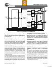
Through the product term allocator, software automatically
distributes product terms among the 16 macrocells in the logic
block as needed. A total of 80 product terms are available from
the local product term array. The product term allocator
provides two important capabilities without affecting perfor-
mance: product term steering and product term sharing.
Product Term Steering
Product term steering is the process of assigning product
terms to macrocells as needed. For example, if one macrocell
requires ten product terms while another needs just three, the
product term allocator will “steer” ten product terms to one
macrocell and three to the other. On Ultra37000 devices,
product terms are steered on an individual basis. Any number
between 0 and 16 product terms can be steered to any
macrocell. Note that 0 product terms is useful in cases where
a particular macrocell is unused or used as an input register.
Product Term Sharing
Product term sharing is the process of using the same product
term among multiple macrocells. For example, if more than
one output has one or more product terms in its equation that
are common to other outputs, those product terms are only
programmed once. The Ultra37000 product term allocator
allows sharing across groups of four output macrocells in a
variable fashion. The software automatically takes advantage
of this capability—the user does not have to intervene.
Note that neither product term sharing nor product term
steering have any effect on the speed of the product. All
worst-case steering and sharing configurations have been
incorporated in the timing specifications for the Ultra37000
devices.
Ultra37000 Macrocell
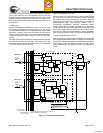
Within each logic block there are 16 macrocells. Macrocells
can either be I/O Macrocells, which include an I/O Cell which
is associated with an I/O pin, or buried Macrocells, which do
not connect to an I/O. The combination of I/O Macrocells and
buried Macrocells varies from device to device.
Buried Macrocell
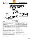
Figure 2 displays the architecture of buried macrocells. The
buried macrocell features a register that can be configured as
combinatorial, a D flip-flop, a T flip-flop, or a level-triggered
latch.
The register can be asynchronously set or asynchronously
reset at the logic block level with the separate set and reset
product terms. Each of these product terms features program-
mable polarity. This allows the registers to be set or reset
based on an AND expression or an OR expression.
Clocking of the register is very flexible. Four global
synchronous clocks and a product term clock are available to
clock the register. Furthermore, each clock features program-
mable polarity so that registers can be triggered on falling as
well as rising edges (see the Clocking section). Clock polarity
is chosen at the logic block level.
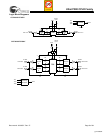
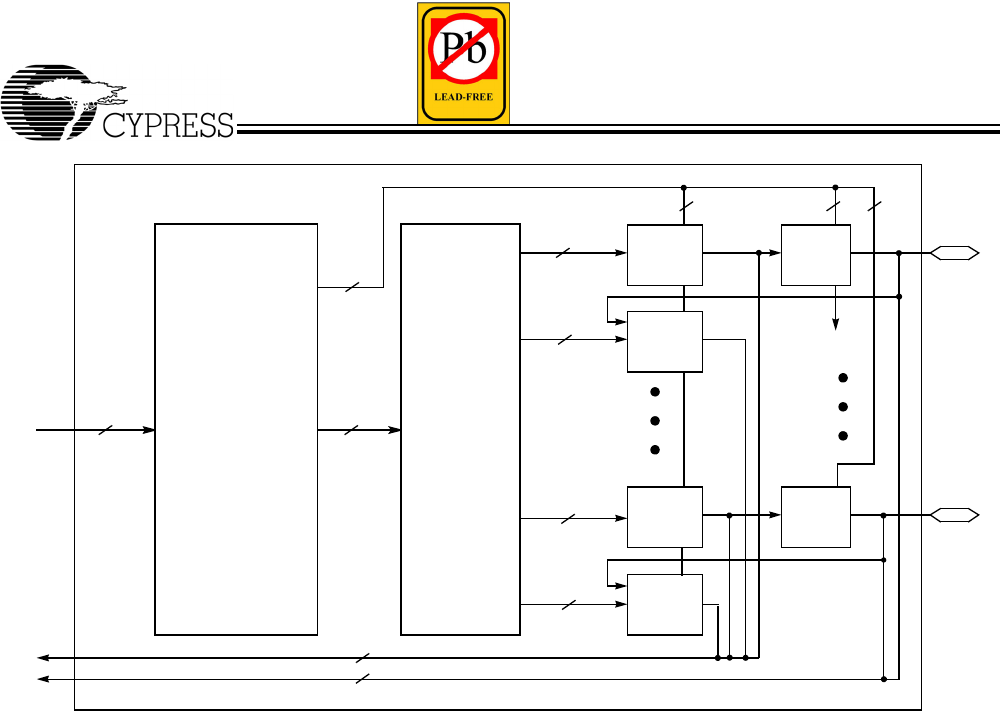
Figure 1. Logic Block with 50% Buried Macrocells
I/O
CELL
0
PRODUCT
TERM
ALLOCATOR
I/O
CELL
14
MACRO-
CELL
0
MACRO-
CELL
1
MACRO-
CELL
14
0−16
PRODUCT
TERMS
72 x 87
PRODUCT TERM
ARRAY
8036
8
16
TO
PIM
FROM
PIM
7
3
2
MACRO-
CELL
15
2
to cells
2, 4, 6 8, 10, 12
0−16
PRODUCT
TERMS
0−16
PRODUCT
TERMS
0−16
PRODUCT
TERMS
[+] Feedback


