


DATALOGIC DS2400
Installation
- 2.3
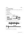
2.3 JUNCTION BOX INSTALLATION
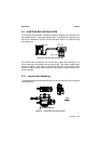
The Junction Box provides a passive connection between your scanner and
the outside world in a fast and practical way. It represents an alternative to
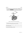
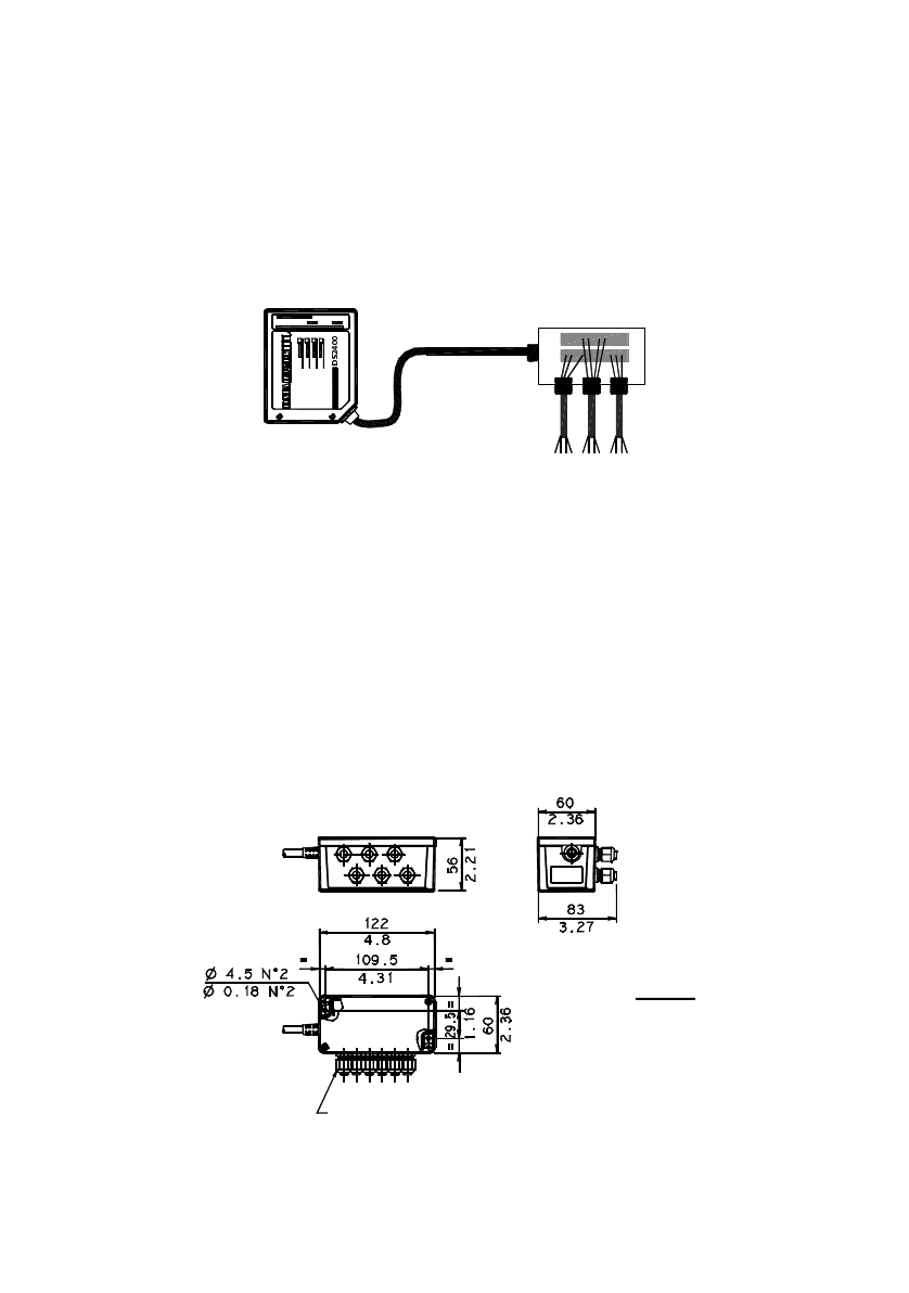
the 25-pin connectors. Figure 2.3 shows the basic layout of a scanner using
the junction box.
Scanner cable
Junction Box
System cables
DS2400
Figure 2.3 - Scanner using Junction Box
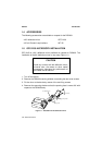
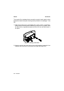
For Junction Box connections, the scanner has a cable that terminates in a
24 pin connector that plugs into the junction box. The system cables pass
through 6 glands in the side of the Junction Box and the individual wires
connect to spring clamp terminal blocks inside which provide access to all
scanner signals.
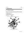
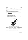
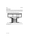
2.3.1 Junction Box Mounting
The diagram below shows the dimensions of the Junction Box and its relative
mounting holes.
mm
inch
GLANDS PG7 n°6
Figure 2.4 - Junction Box Overall dimensions