


DS2400 DATALOGIC
2.6
- Installation
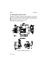
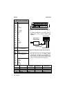
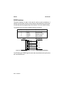
J. Box Pinout for DS2400
Pin Name
01
VS
02
GND
03
VS
04
GND
05
CHASSIS
06
VS
07
VS
08
EXT TRIG +
09
EXT TRIG -
10
GND
11
GND
12
VS
13
VS
14
N.C.
15
N.C.
16
GND
17
GND
18
OUT1 +
19
OUT REF
20
OUT2 +
21
N.C.
22
N.C.
23
N.C.
*24
*25
*26
Main interface signals
see table below
27
N.C.
28
GND
29
30
31
32
33
Main interface signals
see table below
34
GND
35
TXAUX
36
RTSAUX
37
GND
38
RXAUX
39
CTSAUX
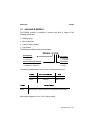
117
18 39
J1
5
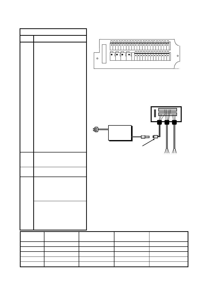
Figure 2.7 - Junction Box connector and pinout
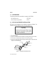
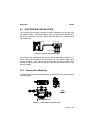
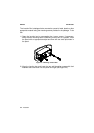
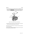
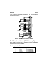
To allow connection of an NEC Class 2
Power Unit, use a correct female plu
g
adapter.
Junction Box
NEC Class 2
Power supply
Female Plug
System cables
Figure 2.8 - NEC Class 2 Power unit connections
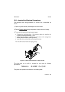
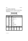
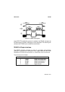
*
The signals on pins 24, 25, and 26 are repeated on
pins 29, 30, and 31 to facilitate network
connections (i.e. Multiplexer using the RS485 Half-
duplex interface). In this way the network bus can
enter and exit the junction box from different spring
clamps but be physically connected together.
Pin RS232 RS485
Full-Duplex
RS485
Half-Duplex
20 mA C.L.
(INT-22 Only)
24,29 TX232 TX485+ RTX485+ CL OUT+
25,30 RTS232 TX485- RTX485- CL OUT-
26,31 SGND SGND SGND
32 RX232 RX485+ CL IN+
33 CTS232 RX485- CL IN-