


DS2400 DATALOGIC
2.8
- Installation
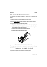
2.4 ELECTRICAL CONNECTIONS
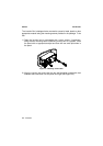
DS2400 25-pin connector models are equipped with a cable terminated by a
25-pin female D-sub connector for connection to the power supply and
input/output signals.
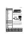
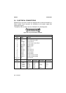
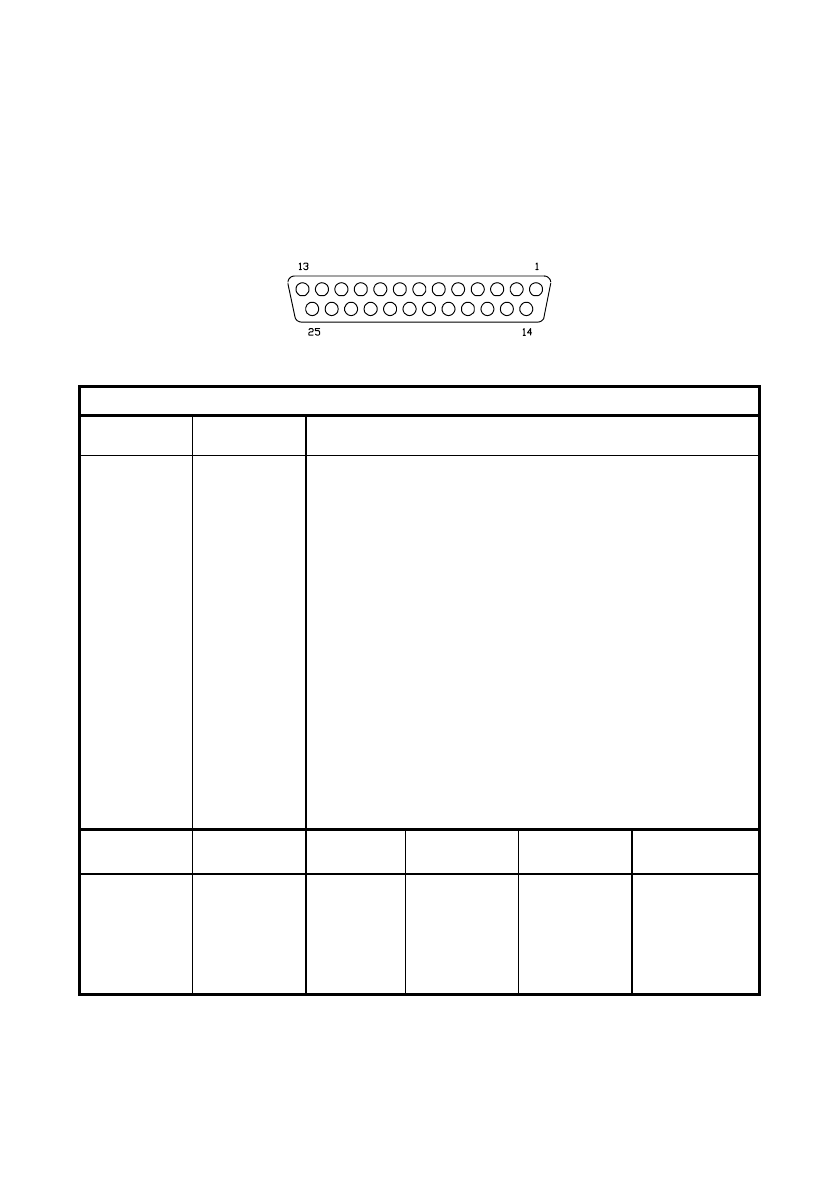
The details of the connector pins are indicated in the following table:
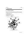
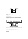
Figure 2.10 - 25-pin female D-sub connector
25-pin D-sub connector pinout
Pin Name Function
13 VS Power supply input voltage +
25 GND Power supply input voltage -
1 CHASSIS Chassis Ground
9 VS External Trigger supply voltage +
18 EXT TRIG+ External Trigger +
19 EXT TRIG- External Trigger -
8 OUT1 + Output 1 +
11 OUT2 + Output 2 +
12 OUT REF Output reference
22 OUT REF Output reference
20 RXAUX Auxiliary RS232
21 TXAUX Auxiliary RS232
23 CTSAUX Auxiliary handshake RS232
24 RTSAUX Auxiliary handshake RS232
6, 10, 14, 15,
16, 17
NC Not Connected
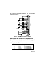
Pin RS232
RS485
Full-Duplex
RS485
Half-Duplex
20 mA C.L.
(INT-22 Only)
2 TX232 TX485+ RTX485+ CLOUT+
3 RX232 RX485+ CLIN+
4 RTS232 TX485- RTX485- CLOUT-
5 CTS232 RX485- CLIN-
7
Main
interface
signals,
see par.
2.4.2.
SGND SGND SGND